robot_localization: unusual behavior when fusing IMU orientation
Hi !
I'm currently working on a mobile robot's localization and I stumbled upon apparently unusual robot_localization behavior.
So I have an IMU mounted sideways with a body frame that follows aircraft conventions (Y-axis to the right, Z-axis down) reporting attitude w.r.t. the local NED frame. The robot base frame uses regular land vehicle conventions (Y-axis to the left, Z-axis up) and, following REP-103, orientations are expected to be in the local ENU frame. If I'm not mistaken, setting the base_link -> imu_link transform to bridge the gap between conventions and non-neutral mounting (i.e. rpy = [pi, 0, pi/2]) and transforming IMU orientation from the NED to the ENU frame should do. However, when fusing IMU orientation data, /odometry/filtered keeps showing an inverted Z-axis (downwards). And changing the base_link -> imu_link transform to only account for the mounting yaw angle (rpy = [0, 0, pi/2]) has no effect whatsoever.
Has anybody run into this before? Am I making a silly mistake here? I have the slight impression it's because of the peculiar treatment IMU orientations get inside robot_localization. Yes, it has to cope with two frames: the (implicit) coordinate frame and the (explicit) mounting frame. But I don't fully understand the reasoning behind this RPY angles' space subtraction and clamping. What's the rationale here?
Edit:
I put together a small repro on Melodic to both better describe the problem I'm seeing and hopefully help solve it.
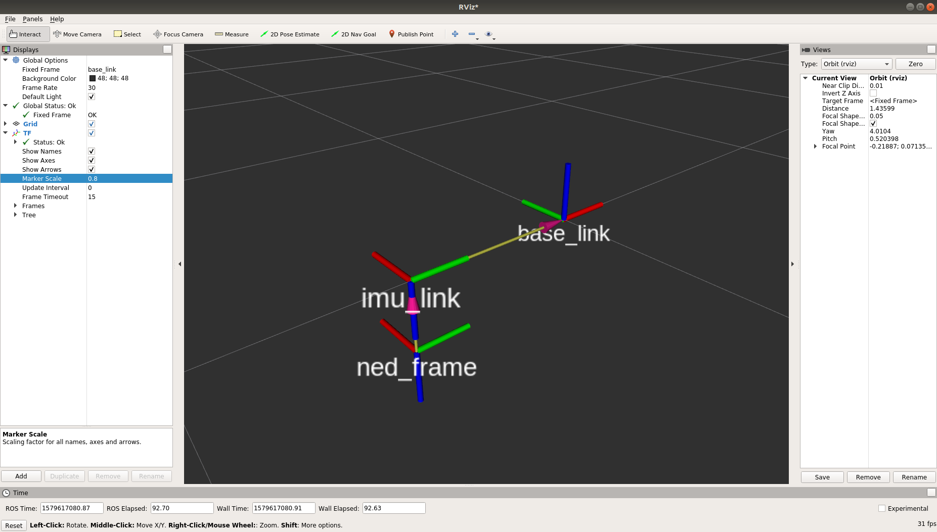
Here you can see how frames relate to each other (NED frame z-axis should probably go through the base COM but you get the point):

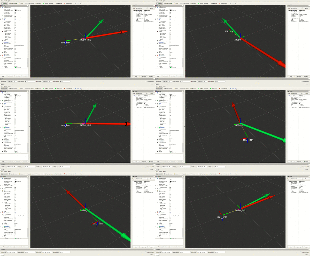
This is what I get when I run said repro:

This does not happen if I simply feed the IMU orientation as it comes (w.r.t the NED frame).
Thanks!


I'm sitting here with my finger-frames, so if we start with something in NED (thumb-down pointer-forward middle-right) and I apply the roll PI, I'm now in the ordinary base-frame coordines. Applying the pi/2 in yaw rotates that body parallel along the ground, not rotating the IMU sideways. Is that potentially an issue or am I misinterpreting your situation?
Memory serves in my experience with flight IMUs I just swapped the sign of the Z and Y signals to get it in the usual mobile-robots frames and then applied the rigid-body transformation for the physical IMU rotation relative to base-frame. Have you tried something like that?
Hmm, I may not have expressed myself correctly. I managed to put together a small repro -- it'll likely be simpler (and less ambiguous/imprecise) to discuss over code. I'll edit the original question as it doesn't seem like I can attach a picture here.
See the attached picture above. That's what I meant by sideways -- IMU body frame x-axis points to the left of the base.
How would that make the IMU orientation correct? An (x, y, z, w) = (0, 0, 0, 1) quaternion w.r.t. the ENU frame means you're heading East while the same quaternion w.r.t. the NED frame means you're heading North. Am I missing something ...(more)
Ah, so you mean its just rotated 90 degrees in plane - that should just be a trival transform once you setup the coordinates correctly.
If you have a RPY from the IMU in the wrong coordinate system, you can swap the signs of the signals for PY angles to create the corrected frame. Then you just have the 90 degree rotation which TF can trivially handle.
Frankly, your added gifs just add more confusion - you need to explain what everything is, what's going on, and what you're trying to display. To me its just a couple rotating angles without annotations about what I'm looking at.
Just want to let you know that I'm not ignoring this question. I have a feeling the answer is going to be pretty involved, because IMUs are evil. In the meantime, can you include a sample message from your IMU in its mounted orientation?
@hidmic Hi, did you end up finding a solution?