ROS Resources: Documentation | Support | Discussion Forum | Index | Service Status | ros @ Robotics Stack Exchange
Ask Your Question
0

SW2URDF how to generate linear axis [closed]

asked 2013-09-09 02:46:11 -0500

Tirgo gravatar image

Hello everyone,

i want to simulate the shifting of several robots on a linear motion system. I´d like them all in one urdf file. I used standard mates to get it on the right position in SolidWorks 2012. Now i can sthift it along the linear motion system. When using the urdf exproter i am defining the motion system (Windkanal) as parent link and the blue part (Roboter_Laser_Schlitten) as child link.
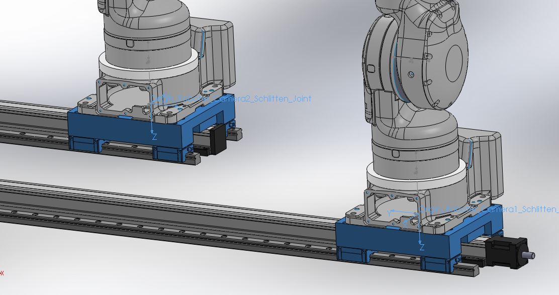
image description

When the blue part is not fixed in the assembly, it does not export any axis or origins at all. I only get the origin_global. When the blue part is fixed it exports the origin of the blue part at least. But, of course, the joint is fixed. Is there any possibility of choosing another joint type and several axis so it will move as i would like it to move?
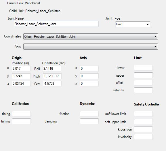
image description

I am going to load the urdf file into moveit setup assistant, just in case this is important.

Thank you all for your help...

edit retag flag offensive reopen merge delete

Closed for the following reason the question is answered, right answer was accepted by Tirgo
close date 2013-09-15 23:56:53

2 Answers

Sort by » oldest newest most voted
1

answered 2013-09-09 05:39:17 -0500

brawner gravatar image

If it's configured correctly, it should be able to calculate the prismatic joint correctly. If it's not, there may be something wrong with your configuration. I would be interested to see more of your tree organization, for example what is your base_link? Maybe there is some structure issue in why the tool isn't automatically calculating the joint.

What you need to define, and you can do this manually, is a prismatic joint between the linear track and its slider (blue thing). In SolidWorks, insert a reference coordinate system ("Insert">"Reference Geometry">"Coordinate System") at the start of the slider's motion, and insert a reference axis along the sliders direction of motion. When setting up the configuration, select the inserted coordinate system for that joint's coordinate system, select the inserted axis for that joint's axis, and select 'prismatic'. A prismatic joint defines a linear motion like you are looking for here.

edit flag offensive delete link more
0

answered 2013-09-11 01:18:00 -0500

Tirgo gravatar image

This already helped a lot. That is all i wanted. Thank you very much.

edit flag offensive delete link more

Question Tools

2 followers

Stats

Asked: 2013-09-09 02:46:11 -0500

Seen: 1,718 times

Last updated: Sep 11 '13