ROS Resources: Documentation | Support | Discussion Forum | Index | Service Status | ros @ Robotics Stack Exchange
Ask Your Question
0

move_base global planner gets close to obstacles

asked 2020-10-08 06:39:00 -0500

nalistic gravatar image

updated 2021-04-24 02:30:47 -0500

miura gravatar image

Hello, I am using ROS for autonmous navigation, I am using the move_base package. The global planner paths are not as expected, i am attaching a screenshot of an example, here 
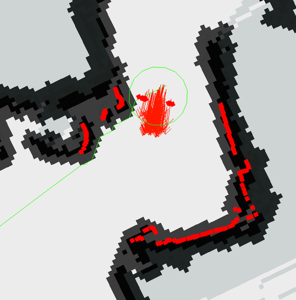
the global planner gets so close to the inflated obstacles like if it was not taking into account the robot radious. is this expected? shouldnt the global planner path be atleast the robot radius from the obstacle?

costmap params

obstacle_range: 2.5
raytrace_range: 3.0
robot_radius: 0.33
inflation_radius: 0.13
observation_sources: laser_scan_sensor
laser_scan_sensor: {sensor_frame: laser, data_type: LaserScan, topic: /scan_filtered, marking: true, clearing: true}

global costmap

global_costmap:
global_frame: /map
robot_base_frame: base_link
update_frequency: 5.0
static_map: true
edit retag flag offensive close merge delete

1 Answer

Sort by ยป oldest newest most voted
2

answered 2020-10-08 08:17:01 -0500

JackB gravatar image

updated 2020-10-08 08:22:44 -0500

Someone please correct me if I am wrong but this is my understanding:

So the Global Planner generates a path, which connects the start and goal point, and does not pass through any occupied cells in the costmap. The Local Planner is responsible for balancing costs associated with staying close to the given global plan, reaching its goal, and avoiding obstacles. It is the local planner which actually generates command velocities and is therefore responsible for the robot, moving, avoiding collision, or having a collision.

That being said, the only information the Global Planner has when you give it a goal, is the global_costmap, and that's it. What it essentially does with that, is a graph search across all possible unoccupied cells, to find a (hopefully short) path that connects the start point to the goal point. During this time it treats the robot as a point object with no shape/structure. This point object "assumption" simplifies the process of calculating the path across a map because it allows us to ignore the shape of the vehicle, the shape of obstacles, and the collision potential of different parts of the vehicle. Because it treats your object as a point, all it has do is check whether or not there is a collision at each cell individually. For large maps this is a huge optimization.

In order to prevent this point approximation being a problem you have to use a InflationLayer on your global_costmap. This makes the obstacles appear larger, and means that our point object approximation will, even when planning right on the edge of what "looks like an obstacle", actually still be in a safe space in the real world. As a rule of thumb I personally set my global_costmap InflationLayer to be about 3/4 the width of my robot.

This is different from the local_planner, which is responsible for generating the command velocities the robot will execute. The local planner generally uses a much shorter planning horizon (2 to 10 meters?) and a much smaller costmap. When it is evaluating potential trajectories that it may command, it will predict forward the position of the robot (accounting for its footprint) and check for collisions with the obstacles found in the local_costmap. It is in the local planning stage where your platform's footprint is actively taken into account. The local planner will balance the cost associated with proximity to obstacle cells, the local end goal point, and the global plan and generate a command velocity that will execute a path that minimizes these costs.

All the global planner did was find a string of connected cells that takes you from the start to the goal, and your local planner actually generates the command velocities that minimize the cost associated with the objective function.

Note: Sorry I did not link directly to more source material :/

edit flag offensive delete link more

Comments

1

This pdfhas a good documentaiton of the navigation stack: http://kaiyuzheng.me/documents/navgui...

GeorgNo gravatar image GeorgNo  ( 2020-10-08 08:22:27 -0500 )edit

Thanks so much! I am taking a look into different planners to see if other suits me more, but one thing i dont fully understand, is, the global path shouldnt be taking into consideration also the radious of the robot? i know that increasing the inflation layer would make it safier, but if i put the robot over the path returned by the planner it would be colliding with the obstacles, because it looks it is not taking into account the radious of the robot itself, only the center

nalistic gravatar image nalistic  ( 2020-10-08 08:35:22 -0500 )edit
1

That is exactly the situation I describe in my answer:

"That being said, the only information the Global Planner has when you give it a goal, is the global_costmap, and that's it. What it essentially does with that, is a graph search across all possible unoccupied cells, to find a (hopefully short) path that connects the start point to the goal point. During this time it treats the robot as a point object with no shape/structure. This point object "assumption" simplifies the process of calculating the path across a map because it allows us to ignore the shape of the vehicle, the shape of obstacles, and the collision potential of different parts of the vehicle. Because it treats your object as a point, all it has do is check whether or not there is a collision at each cell individually. For large maps this is a huge optimization."

JackB gravatar image JackB  ( 2020-10-08 08:40:43 -0500 )edit

Ok thanks ill try and come back with my results!

nalistic gravatar image nalistic  ( 2020-10-08 08:42:22 -0500 )edit

Hello, I'm having the same issue . and I 'm using an inflation layer but no success ... Do you have any other Solution ?

hediimohamed gravatar image hediimohamed  ( 2021-04-07 06:04:25 -0500 )edit

Hello, we ended up increasing the inflation layer to be the same as the robot radius itself, I am not sure if this was the best solution, but it worked perfectly. At first i thought that if the robot radius was 33 and inflation layer 13, the robot would not fit in a 45 cm corridor, but no, the radius of the robot wasnt being taken into account and increasing the inflation layer to 35 (I dont remember the exact values) worked fine

nalistic gravatar image nalistic  ( 2021-04-07 06:28:03 -0500 )edit

ok, Thank you !

hediimohamed gravatar image hediimohamed  ( 2021-04-07 06:36:33 -0500 )edit

Question Tools

3 followers

Stats

Asked: 2020-10-08 06:39:00 -0500

Seen: 1,986 times

Last updated: Oct 08 '20