
Why Hector-Slam works better than Gmapping with RPLiDAR?
Hi. I am working with a home-made differential robot that have a RPLiDAR sensor for SLAM. Initially it worked with Hector-Slam a i had quiet good results, but now i am trying to improve them with Gmapping. I follow this turorial for setting up the parameters of Gmapping. Then i record a bag and when a i make my map with Gmapping i get a worst result than the one provided by hector. The Hector's result is this one Hector, and Gmapping
I tryed to follow the solution propose in this question but it didn't work.
I think that my problem is related with my frames despite i follow the specifications explained here.My tf tree is this one.
I am trying to upload the maps generated by both algorithms but i cant because i don't have five points, and i don't know how to earn them.
Thanks for your help
EDIT
My new tf tree is the next one 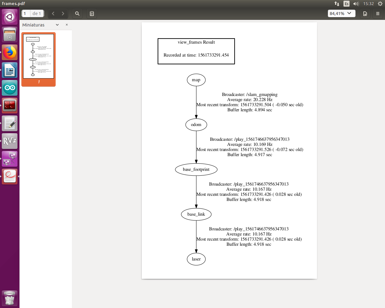
And the new map made by gmapping its the next one.
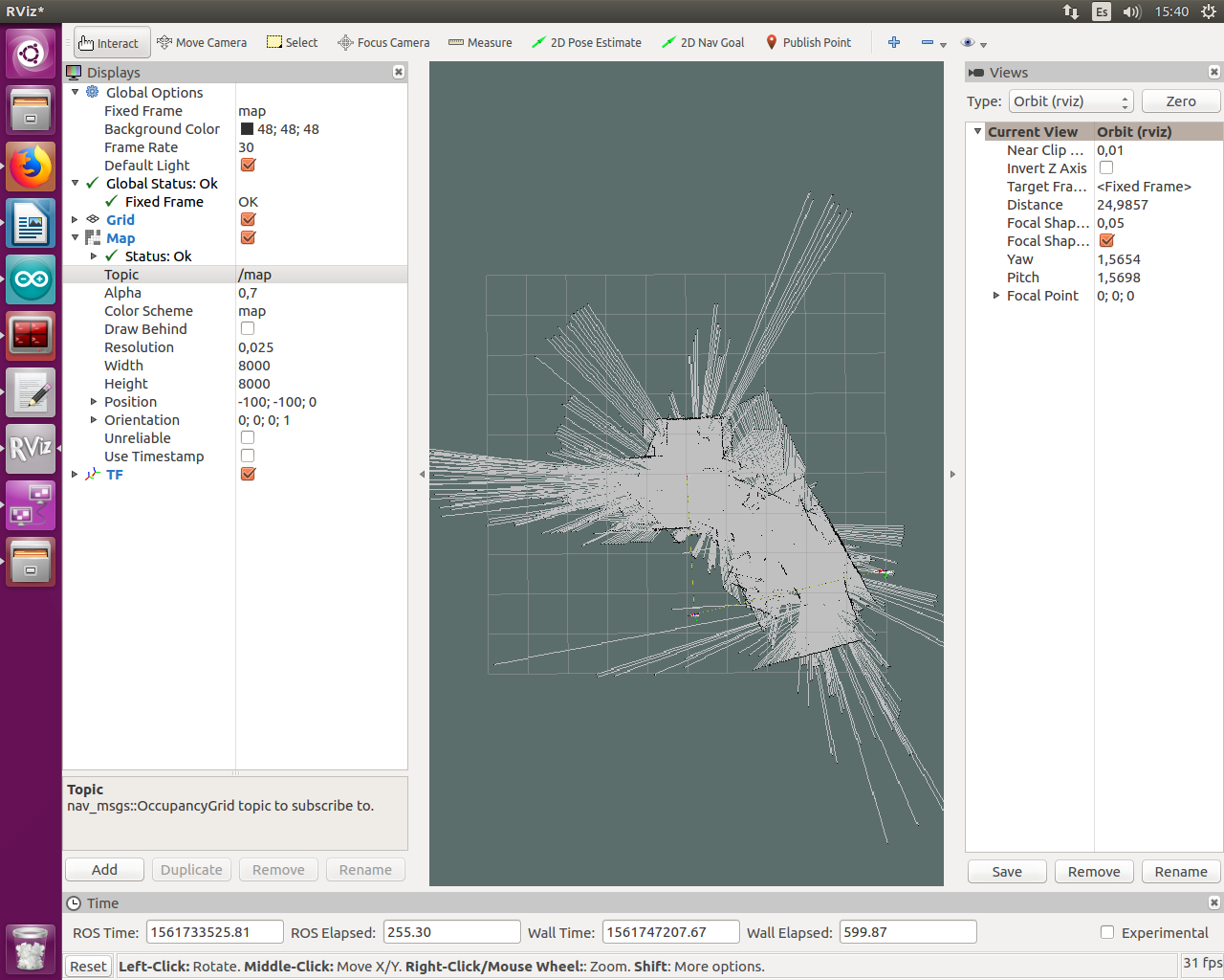
Hector slam still have a better look.
EDIT 2
The commands that i use in my projects are the next ones:
//Terminal 1
roscore

//Terminal 2
export ROS_IP=163.10.76.106

//Terminal 3 - This one runs the RpLidar node
ssh -X blasrobot@10.0.12.237//probar sino la  10.0.12.237
export ROS_MASTER_URI=http://163.10.76.106:11311
export ROS_IP=10.0.12.237
ls -l /dev |grep ttyUSB
sudo chmod 666 /dev/ttyUSB0
cd catkin_ws/
source devel/setup.bash
roslaunch rplidar_ros rplidar.launch

//Terminal 4  - This one gives me back the static transforms and the odometry data as the odom->base_link transform
ssh -X blasrobot@10.0.12.237
export ROS_MASTER_URI=http://163.10.76.106:11311
export ROS_IP=10.0.12.237
sudo chmod a+rw /dev/ttyACM0
rosrun rosserial_python serial_node.py _port:=/dev/ttyACM0 _baud:=57600

//Terminal 5 - This one sends speed to the robot
ssh -X blasrobot@10.0.12.237
export ROS_MASTER_URI=http://163.10.76.106:11311
export ROS_IP=10.0.12.237
rostopic pub -r 10 /cmd_vel geometry_msgs/Twist '[0.0, 0, 0]' '[0, 0, 0]'

//Terminal 6 - This one runs the gmapping node
cd catkin_ws/
source devel/setup.bash
rosrun gmapping slam_gmapping scan:=scan
EDIT 2
After some debugging i realized that my problem is with my odometry. I run the two sanity check provided here and i get the next results:
Straight Foward:
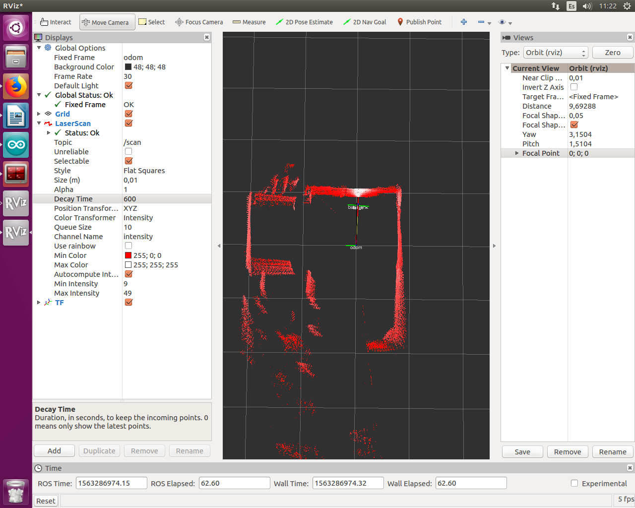
Rotation:
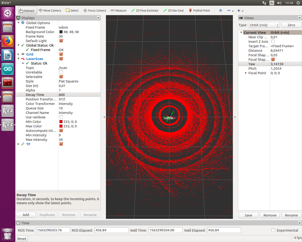
After watching this it is obvious that my problem came from my odometry while rotations. I checked the model and the parameters are okey. Any idea?

Can you provide some info how you get the odometry from the robot?
Hi Ktysai. Thanks for answering. Sorry for the delay, but i was abroad. To get my odometry i am using two encoders. With each tick of each encoder I generate an interruption and using timers i count how many counts of the timer i have (with the TCNTx register). with this counts i calculate the speed as: Input2 = 2 * PI / 1120 / paso2 / 5 * 10000000 (where paso2 is the number of counts and " /5 * 10000000 " is because i set the timers to have a count each 500ns).
Once i calculate the speed of each motor, i use the following relationships:
vx = R / 2 * (Input1 + Input2) * cos(th);
vy = R / 2 * (Input1 + Input2) * sin(th);
vth = R / L * (Input1 - Input2);
//Calculo posicion
x = x + vx * deltat;
y = y + vy * deltat;
th = th + vth * deltat;
Where deltat is the loop time.
Have you tried vth = R/L * (Input2 - Input1);? Depending on how you name your joints you can have left and right encoder inverted. In my robot I do vth = R/L * (input_right - input_left);. When traveling on a straight line the influence of this inversion is not too big, but it is obvious when spinning.
Martin, finally i improve my odometry while spinning changing the way i calculate the angle. I just calculate it from encoder's ticks.