
map problems with gmapping
Hello all
i have a lidar lite v3 i rotate it with stepper motor to get planner lidar. i wrote a driver node, use it with gmapping node and odometry node. i get bad maps. they differ in each rotation. map image is attached.
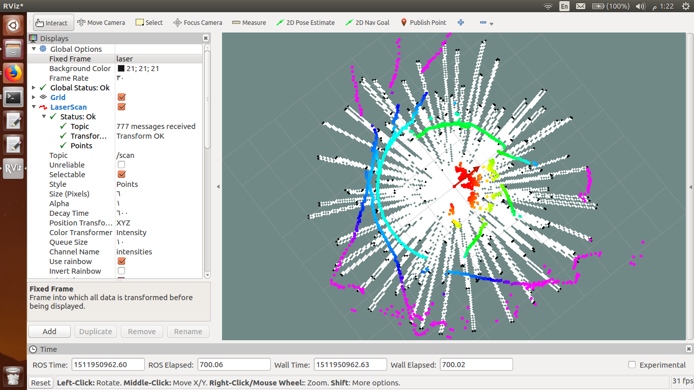

seems you have set your decay time to something :-)
What is the output of one single message of the laser? The way it looks, there seems something very wrong with your driver. But this could also be due to the decay time in the image...
@mig the output of laser is a point. i do not know what is wrong with it! the decay time lets points to stay visual more time (as i understand it)
How fast are you turning? Fast turns can result in bad maps.
@jayess how to calculate it ?
Well, you are driving it right? So you know how fast you're telling it to go? You don't need to calculate the speed. Just keep in mind that if you're getting bad results during a turn then you need to turn slower.
@jayess i don't drive the robot yet. the lidar rotates in its place. my stepper motor type is slow in its nature. it is 28BYJ-48.
How are you syncing the rotation of the laser to the scan message? The scan message format assumes that the first measurement in the message is at whatever angle the header indicates is the start. It looks like you do not sync measurements with rotation, or that the sync is not working correctly.
@billy i am using ros driver from here driver i edited it to be familiar with my lidar and stepper
OK, Are you using the arduino code from github also? If so, are you sure the motor steps/revolution agree with the code?
What have you done to troubleshoot?
@billy yes, i just edit the arduino code to work with lidar V3 for the steps i am using an approximate number, when i use the steps from datasheet i get overlapping circles.
to troubleshoot what ?
To isolate bad data vs rotation sync issues, I suggest you disconnect the stepper from the driver so the lidar doesn't physically rotate. If everything else is working you should get a clean circle in RVIZ since the LIDAR should be reporting only one value. If a circle, you have likely sync issue.
@billy if i connect the lidar alone without rotation i get circles
That's a good data point. Now replace the LIDAR data in the arduino and send fake data with a pattern. Maybe start each rotation at a value of 100 and increase by 1 each data point to 460, then start again at 100. This should provide a spiral pattern. If not, your data isn't sycned with the angle.
continued...How do you sense and how do you indicate the start of each rotation? Do you have a sensor that signals the zero point of the rotating part? Like an index or something? There must be something in the arduino code that reads the angle at least once per revolution.
@billy i do not get how to replace data by fake one?
@billy i have these lines in arduino code is it what you mean by zero index?
void stepmotor( void )
{
  digitalWrite(pin_step, HIGH);
 // Serial.print(motorStepCnt);
  if ( ++motorStepCnt > stepsPerRevolution )
  {
    motorStepCnt = 0;
  }
  digitalWrite(pin_step, LOW);
}