The site is read-only. Please transition to use Robotics Stack Exchange
| ROS Resources: Documentation | Support | Discussion Forum | Index | Service Status | ros @ Robotics Stack Exchange |
| 2020-11-23 08:25:33 -0500 | received badge | ● Nice Question (source) |
| 2015-10-27 06:26:08 -0500 | received badge | ● Good Question (source) |
| 2015-10-27 06:26:02 -0500 | received badge | ● Favorite Question (source) |
| 2014-06-02 07:50:29 -0500 | received badge | ● Famous Question (source) |
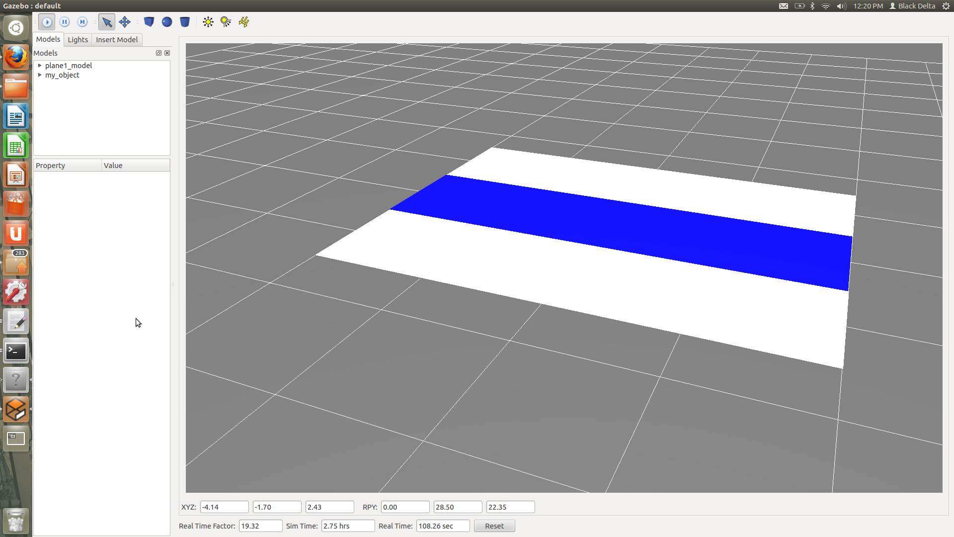
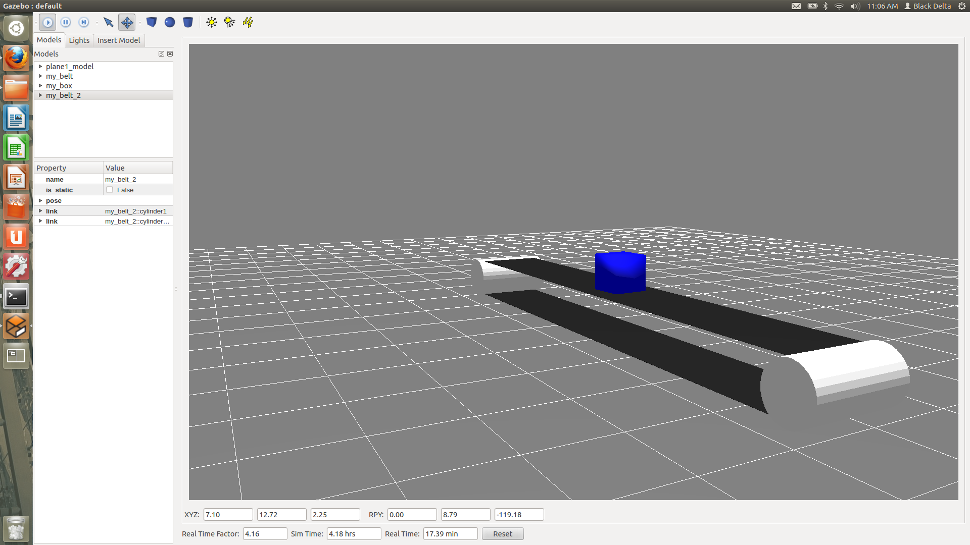
| 2014-01-28 17:29:30 -0500 | marked best answer | Manipulating Position of Conveyor Belt relative to platform in Gazebo and applying body wrench Hello Everyone, I created a simple conveyor model in RVIZ (see URDF below) The plan was to have the blue strip much longer in the y direction so that when it moved, it simulated a conveyor for a long period of time. When I simulated this in RVIZ with the slide for the prismatic joint, the model worked and the belt moved. Now I need to make a conveyor simulation in Gazebo and I accomplished this before by exerting a force on a different belt, see answer to this question: http://answers.ros.org/question/52309/defining-joints-in-solidworks-to-urdf-exporter-for-a-conveyor-belt/ Trying to do what I did before, I spawned this Object in gazebo (added in gazebo reference for color):
and applied the wrench on the blue belt: However, it would not move. I need to have this belt move and effect other robots in gazebo (so that the robots do not move it, but it moves other robots), and I do not know what the best way to have this done is. I also looked into plugin tutorials, but when I tried it, I was getting errors, so before I go that route, I want to know if there is a simpler way of doing this. I figured if I have the white platforms surrounding the belt, the robots on the platform/belt will not move the belt relative to the world, but will be effected by the belt's movement. Am I applying the wrench wrong/making some mistake or is there no simple ... (more) |
| 2014-01-28 17:28:44 -0500 | marked best answer | Defining Joints in Solidworks to URDF Exporter for a Conveyor Belt Dear all, I am trying to create a working conveyor belt in Gazebo. I built a conveyor in SolidWorks and used the Solidworks to URDF Exporter to generate the URDF file. The belt appears in Gazebo just fine, but I cannot get it to actually move when effort is applied to a Cylinder. Image of Conveyor Belt in Question:
I think the problem is my definition of links and joints in the Solidworks to URDF Exporter (and the URDF file that is generated). Here us the URDF File: Does anyone know how I would define joints and links in SW to URDF Exporter/ URDF in order for the belt to move when torque is applied on one of the cylinders? I also tried applying joint effort using this: Thank you for your help! |
| 2014-01-28 17:28:40 -0500 | marked best answer | No color when I open a part exported from SolidWorks in Gazebo? Hello Everyone! I am trying to create a conveyor belt simulation in gazebo, using the SolidWorks to URDF exporter. Before importing the conveyor, I decided to test the exporter out on a simple part, and I managed to spawn it in Gazebo just fine, but no matter what I do, I cannot seem to get any color but white/gray. Tried the following: Changing texture in URDF Exporter, changing the RGB values in URDF file, changing colors and textures in SolidWorks before exporting. Am I doing something wrong? Thank you for your time! Example URDF generated from a extruded pink cube in solidworks. (not edited) |
| 2013-07-28 17:36:32 -0500 | received badge | ● Famous Question (source) |
| 2013-07-24 22:55:54 -0500 | received badge | ● Taxonomist |
| 2013-07-24 08:43:52 -0500 | received badge | ● Famous Question (source) |
| 2013-05-23 22:46:44 -0500 | received badge | ● Good Answer (source) |
| 2013-05-23 22:03:32 -0500 | received badge | ● Notable Question (source) |
| 2013-04-25 06:58:36 -0500 | received badge | ● Famous Question (source) |
| 2013-04-11 03:27:24 -0500 | received badge | ● Notable Question (source) |
| 2013-04-10 03:01:00 -0500 | commented answer | Working with a new usb-connected device on Robot in ROS? Thank you! It does give me a more clear picture! |
| 2013-04-09 23:10:55 -0500 | received badge | ● Famous Question (source) |
| 2013-04-09 04:58:30 -0500 | received badge | ● Popular Question (source) |
| 2013-04-09 04:05:45 -0500 | received badge | ● Organizer (source) |
| 2013-04-09 04:04:37 -0500 | asked a question | Working with a new usb-connected device on Robot in ROS? Hey all, My goal is to have a robot output its current movement and let LEDs know when to flash, indicating that the care-o-robot is moving. I will be connecting a new LED through a USB port on the robot, but first I want to get this working in a Gazebo simulator. The way I see it (and I may be wrong), I will need to do the following: 1) Create a node that listens to robot's base 2) Have that node output "on" or "off" to the LED connected through a USB I am new to ROS and a little overwhelmed by the amount of tutorials. I am not sure where to look for relevant information... Are there any tutorials that are specifically dedicated to creating new nodes for a robot? How to make that node communicate with another node on the robot? How to define that node as the Digital Output for the LED? I read through the general node tutorials, but when I dig through Care-o-Bot files, I find files far more complex than in the tutorial. I know this is a lot of questions, but if you could give some advice on at least one of them, I would be very thankful! General advise is appreciated as well! |
| 2013-04-03 04:49:53 -0500 | received badge | ● Notable Question (source) |
| 2013-04-03 04:49:53 -0500 | received badge | ● Popular Question (source) |
| 2013-04-02 02:36:41 -0500 | asked a question | Adding a projector to the robot in simulation? Dear all, I need to model a robot that has either a projector or LEDs on board that light up at certain times, and I am having a hard time getting started. Are there any tutorials as to how to model a component that was added to the robot and have it act based off robot's output? If you have any suggestions, I would highly appreciate them! Thank you! |
| 2013-04-02 01:35:34 -0500 | received badge | ● Famous Question (source) |
| 2013-03-04 19:34:37 -0500 | received badge | ● Famous Question (source) |
| 2013-03-04 18:55:13 -0500 | received badge | ● Popular Question (source) |
| 2013-03-01 01:06:50 -0500 | asked a question | Friction properties in Gazebo Hey all, I was wondering if someone could explain how friction works in Gazebo. I noticed that for robots like PR2, friction properties are defined for joints rather than for links. How can I define friction properties for the object itself and not for a specific joint between two objects? Let's say I have a belt and I define friction between a belt and some other object in URDF. I can add this to the joint: However, if I want the belt and any object that I potentially import/drive on it to have friction between them, how do I do it? Thank you! |
| 2013-02-14 05:27:04 -0500 | received badge | ● Notable Question (source) |
| 2013-02-14 03:24:09 -0500 | commented question | No color when I open a part exported from SolidWorks in Gazebo? Thank you! For now, the fix suggested by Benjamin does the trick. |
| 2013-02-13 13:11:38 -0500 | received badge | ● Famous Question (source) |
| 2013-02-12 02:07:27 -0500 | received badge | ● Notable Question (source) |
| 2013-02-02 13:40:59 -0500 | received badge | ● Popular Question (source) |
| 2013-02-02 07:49:00 -0500 | commented answer | Gazebo object with wheels just keeps rolling when force is applied? Thank you for responding! I just added information to my question above, showing pieces of URDF file. I did have the friction and damping component in the joints, but it did not help. |
 ROS Answers is licensed under Creative Commons Attribution 3.0 Content on this site is licensed under a Creative Commons Attribution Share Alike 3.0 license.