| 2019-05-10 06:26:42 -0500 | received badge | ● Famous Question
(source)
|
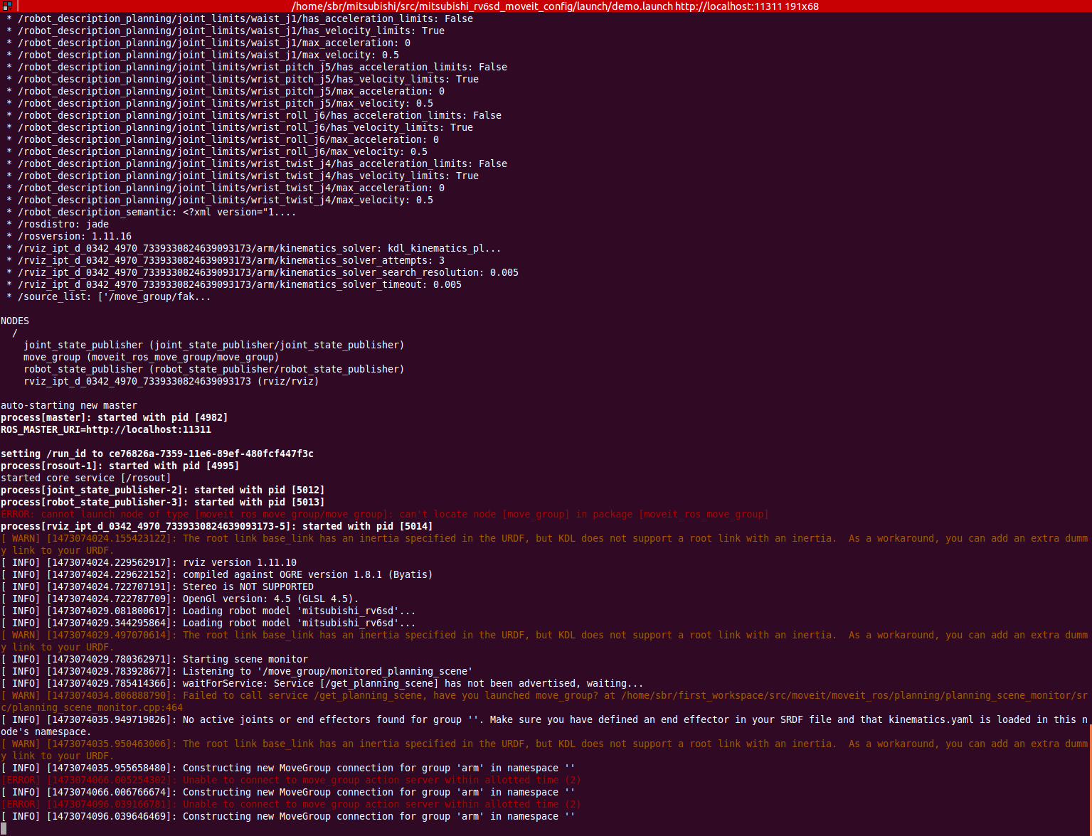
| 2018-06-15 17:26:22 -0500 | marked best answer | MoveIt demo.launch error Hi, I have used the setup assistant of MoveIt to create the config package and it worked fine. But when I launched the demo.launch file, I got the following error : ...
auto-starting new master
process[master]: started with pid [43949]
ROS_MASTER_URI=http://localhost:11311
setting /run_id to eb76e8ea-711b-11e6-8339-480fcf447f3c
process[rosout-1]: started with pid [43963]
started core service [/rosout]
process[joint_state_publisher-2]: started with pid [43980]
process[robot_state_publisher-3]: started with pid [43981]
ERROR: cannot launch node of type [moveit_ros_move_group/move_group]: can't locate node [move_group] in package
[moveit_ros_move_group]
process[rviz_ipt_d_0342_43937_3307353756922455826-5]: started with pid [43982]
[ WARN] [1472827541.765044325]: The root link base_link has an inertia specified in the URDF, but KDL does not
support a root link with an inertia. As a workaround, you can add an extra dummy link to your URDF.
The URDF works perfectly fine with RViZ and Joint State Publisher GUI sliders (without MoveIt) and after a while I get the interactive markers in RViZ (with MoveIt) and I am able to move the arm around but it says 'No Planning Library Loaded'. Also system dependencies seem to be satisfied. I'm unable to find out what the exact issue is. EDIT : I did binary installation of the MoveIt for Jade. I used this link to install MoveIt. Then I launched the setup assistant and created the config package following this video. Here are the screenshots of RViz and Terminal after launching demo.launch : 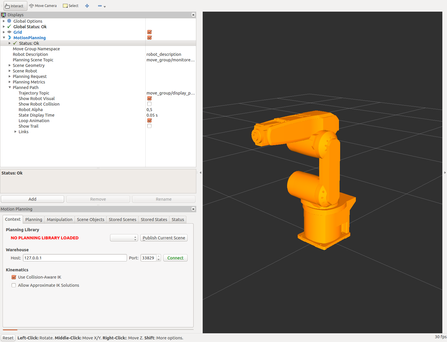
|
| 2018-04-29 22:08:05 -0500 | marked best answer | MoveIT Package for an Industrial Robot I was following the tutorial on using the MoveIt Setup Assistant to create a MoveIt package for an industrial Robot. In the Add Planning groups section, it is mentioned that adding a Kinematic Chain is generally preferred over add joints or add links. But in this MoveIt tutorial, they use the Add Joints for the planning group right_arm and Add Links for the right_gripper group. I want to know what is the difference between these two approaches. Which one is better and in what situation? Thanks for all inputs! |
| 2017-12-21 07:07:14 -0500 | received badge | ● Famous Question
(source)
|
| 2017-09-13 19:34:46 -0500 | marked best answer | MoveIt Attach Object Error Here is my node to add an object and attach it to the robot : #include <moveit/move_group_interface/move_group.h>
#include <moveit/planning_scene_interface/planning_scene_interface.h>
#include <geometric_shapes/shape_operations.h>
using namespace Eigen;
int main(int argc, char **argv)
{
ros::init(argc, argv, "add_workpiece_wall");
ros::NodeHandle nh;
ros::AsyncSpinner spin(1);
spin.start();
moveit::planning_interface::PlanningSceneInterface current_scene;
sleep(2.0);
Vector3d b(0.001, 0.001, 0.001);
moveit_msgs::CollisionObject co;
co.id = "workpiece_wall";
shapes::Mesh* m = shapes::createMeshFromResource("package://mitsubishi_rv6sd_support/meshes/workpiece_wall.stl",b);
ROS_INFO("Workpiece Wall mesh loaded");
shape_msgs::Mesh mesh;
shapes::ShapeMsg mesh_msg;
shapes::constructMsgFromShape(m, mesh_msg);
mesh = boost::get<shape_msgs::Mesh>(mesh_msg);
co.meshes.resize(1);
co.mesh_poses.resize(1);
co.meshes[0] = mesh;
co.header.frame_id = "base_link";
co.mesh_poses[0].position.x = 0.560651;
co.mesh_poses[0].position.y = 0.579113;
co.mesh_poses[0].position.z = 0.0;
co.mesh_poses[0].orientation.w= 0.0;
co.mesh_poses[0].orientation.x= 0.0;
co.mesh_poses[0].orientation.y= 0.0;
co.mesh_poses[0].orientation.z= 0.0;
co.meshes.push_back(mesh);
co.mesh_poses.push_back(co.mesh_poses[0]);
co.operation = co.ADD;
std::vector<moveit_msgs::CollisionObject> abc;
abc.push_back(co);
ROS_INFO("Workpiece Wall added into the world");
current_scene.addCollisionObjects(abc);
sleep(5.0);
moveit::planning_interface::MoveGroup g("arm");
ROS_INFO("Attach Workpiece Wall to the robot");
g.attachObject(co.id);
// Sleep to give Rviz time to show the object attached (different color).
sleep(4.0);
ros::shutdown();
return 0;
}
And the error I'm getting is this: terminate called after throwing an instance of 'std::runtime_error'
what(): No Trajectory execution capability available.
[add_workpiece_wall-7] process has died [pid 47204, exit code -6, cmd /home/sbr/mitsubishi/devel/lib/mitsubishi_rv6sd_support/add_workpiece_wall __name:=add_workpiece_wall __log:=/home/sbr/.ros/log/d1c6e840-9ac0-11e6-ba06-480fcf447f3c/add_workpiece_wall-7.log].
log file: /home/sbr/.ros/log/d1c6e840-9ac0-11e6-ba06-480fcf447f3c/add_workpiece_wall-7*.log
From my previous question it is somewhat clear that the error is only because of these lines : moveit::planning_interface::MoveGroup g("arm");
ROS_INFO("Attach Workpiece Wall to the robot");
g.attachObject(co.id);
// Sleep to give Rviz time to show the object attached (different color).
sleep(4.0);
|
| 2017-07-28 22:12:10 -0500 | received badge | ● Famous Question
(source)
|
| 2017-07-27 12:05:13 -0500 | received badge | ● Famous Question
(source)
|
| 2017-04-28 15:12:35 -0500 | received badge | ● Famous Question
(source)
|
| 2017-04-13 21:29:53 -0500 | received badge | ● Notable Question
(source)
|
| 2017-03-28 01:39:01 -0500 | received badge | ● Popular Question
(source)
|
| 2017-03-24 09:57:17 -0500 | asked a question | Collision Checking between collision object and object attached to the robot Hi, I have writen a node for attaching a collision object to the planning scene. I am using the Apply Planning Scene service for that. Here is my node: Vector3d b(0.001, 0.001, 0.001);
moveit_msgs::AttachedCollisionObject attached_object; // to attach the object to the robot
moveit_msgs::CollisionObject remove_object; // to remove the object from the world
geometry_msgs::Pose pose;
moveit_msgs::PlanningScene planning_scene;
attached_object.link_name = "tool0"; //the link to which the object will be attached
attached_object.object.header.frame_id = "tool0"; // w.r.t. the link to which it is attached
attached_object.object.operation = attached_object.object.ADD;
std::string touch_links = "motor";
attached_object.touch_links.push_back(touch_links);
ROS_INFO("Attaching kinematic_e1 to motor and removing it from the world.");
attached_object.object.id = "kinematic_e1";
shapes::Mesh* m = shapes::createMeshFromResource("package://mitsubishi_rv6sd_support/meshes/objects/kinematic_e1.stl",b);
shape_msgs::Mesh mesh;
shapes::ShapeMsg mesh_msg;
shapes::constructMsgFromShape(m, mesh_msg);
mesh = boost::get<shape_msgs::Mesh>(mesh_msg);
pose.orientation.w = 1.0;
attached_object.object.meshes.push_back(mesh);
attached_object.object.mesh_poses.push_back(pose);
remove_object.id = "kinematic_e1";
remove_object.header.frame_id = "base_link";
remove_object.operation = remove_object.REMOVE;
planning_scene.world.collision_objects.clear();
planning_scene.world.collision_objects.push_back(remove_object); //This step removes the object from the world
planning_scene.robot_state.attached_collision_objects.push_back(attached_object); //This step attaches the object to the robot
planning_scene.is_diff = true; //Update the planning scene as a diff
planning_scene.robot_state.is_diff = true; //Update the robot state as a diff
//Using services to make changes to the planning scene
ros::ServiceClient planning_scene_diff_client = node_handle.serviceClient<moveit_msgs::ApplyPlanningScene>("apply_planning_scene");
planning_scene_diff_client.waitForExistence();
moveit_msgs::ApplyPlanningScene srv;
srv.request.scene = planning_scene;
planning_scene_diff_client.call(srv);
Then I try to check the AllowedCollisionMatrix for the attached object (kinematic_e1 in this case). I use the GetPlanningScene service to get a copy of the allowed collision matrix. But when I query the entry names in the matrix, I cannot find the name of the attached object in the list. moveit_msgs::PlanningScene currentScene;
moveit_msgs::GetPlanningScene scene_srv;
scene_srv.request.components.components = scene_srv.request.components.ALLOWED_COLLISION_MATRIX;
if(!client_get_scene_.call(scene_srv))
{
ROS_WARN("Failed to call service /get_planning_scene");
}
else
{
ROS_INFO_STREAM("Initial scene!");
currentScene = scene_srv.response.scene;
moveit_msgs::AllowedCollisionMatrix currentACM = currentScene.allowed_collision_matrix;
ROS_ERROR_STREAM("size of acm_entry_names before " << currentACM.entry_names.size());
for (int i = 0; i < currentACM.entry_names.size(); i++)
ROS_ERROR_STREAM(" Name = " << currentACM.entry_names[i]);
ROS_ERROR_STREAM("size of acm_entry_values before " << currentACM.entry_values.size());
ROS_ERROR_STREAM("size of acm_entry_values[0].entries before " << currentACM.entry_values[0].enabled.size());
How can I find the attached object in the allowed collision matrix? I dont know if this is related but when I give a pose goal where a definite collision between the robot and the robot attached link wil occur, the planning fails. This kind of tells me that MoveIt! plans taking into consideration the attached object. It appears correctly in RViz as well. Then why does the name of the attached object not show up in the allowed collision matrix? |
| 2017-03-18 12:11:55 -0500 | received badge | ● Famous Question
(source)
|
| 2017-03-18 08:01:28 -0500 | received badge | ● Notable Question
(source)
|
| 2017-03-13 18:59:46 -0500 | answered a question | Hi Guys! Can we give cartesian coordinates as input using MoveIt KDL or any package? As mentioned in this answer and the links given in it, KDL will work well for DOF more than 5. Since you have a 4 DOF arm, you can try to create an IKFast plugin following this tutorial. It seems that IKFast will suit your application better. |
| 2017-01-31 11:03:00 -0500 | commented question | Joint axes problem in urdf The links don't have any origin element. Have you checked the geometric origins for the links? Refer to the answer and comments in this question to see if it helps. Also if possible please share the RViz screenshot. |
| 2017-01-31 11:00:51 -0500 | marked best answer | URDF Links and Joints Orientation I have created a URDF file for my six axis robot manipulator. I can launch it to visualize it in rviz via a launch file. Here is how it looks in rviz : 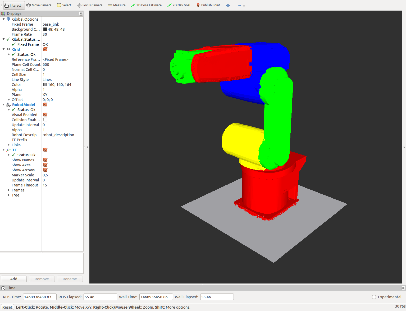 When I try to move the manipulator using the Joint State Publisher, only the first joint moves at the origin along it's axis. The other links deviate from the origin. It looks like this : 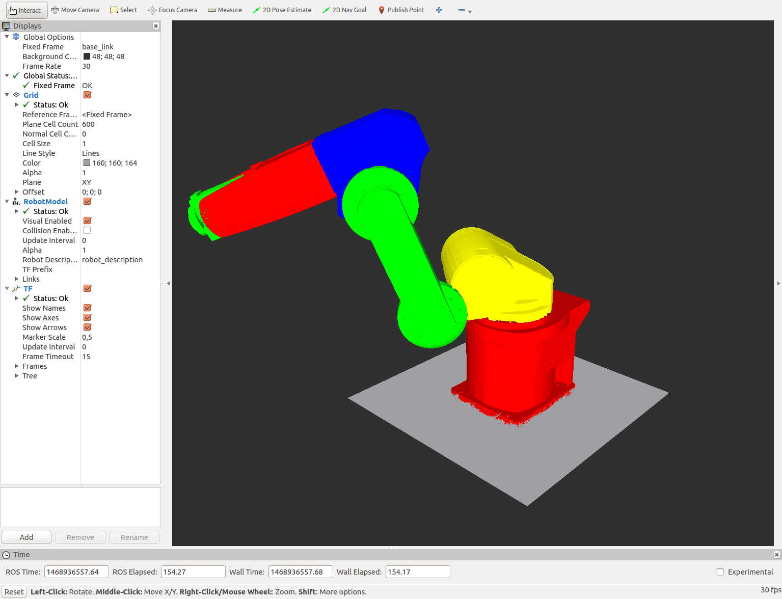 My URDF file is as follows : <?xml version="1.0"?>
<robot name="Mitsubishi_rv-6sd">
<!-- ...................Material Definitions............................................ -->
<material name="blue">
<color rgba="0 0 1 1"/>
</material>
<material name="black">
<color rgba="0 0 0 1"/>
</material>
<material name="white">
<color rgba="1 1 1 1"/>
</material>
<material name="red">
<color rgba="0.8 0 0 1"/>
</material>
<material name="green">
<color rgba="0 1 0 1"/>
</material>
<material name="yellow">
<color rgba="1 1 0 1"/>
</material>
<!---............................. Link Definitions ................................-->
<link name="base_link">
<visual>
<geometry>
<mesh filename="package://demo/meshes/Final/body0.stl"/>
</geometry>
<origin rpy="0 0 0" xyz="0 0 0"/>
<material name ="red"/>
</visual>
</link>
<link name="body1">
<visual>
<geometry>
<mesh filename="package://demo/meshes/Final/body1.stl"/>
</geometry>
<origin rpy="0 0 0" xyz="0 0 0"/>
<material name ="yellow"/>
</visual>
</link>
<link name="body2">
<visual>
<geometry>
<mesh filename="package://demo/meshes/Final/body2.stl"/>
</geometry>
<origin rpy="0 0 0" xyz="0 0 0"/>
<material name ="green"/>
</visual>
</link>
<link name="body3">
<visual>
<geometry>
<mesh filename="package://demo/meshes/Final/body3.stl"/>
</geometry>
<origin rpy="0 0 0" xyz="0 0 0"/>
<material name ="blue"/>
</visual>
</link>
<link name="body4">
<visual>
<geometry>
<mesh filename="package://demo/meshes/Final/body4.stl"/>
</geometry>
<origin rpy="0 0 0" xyz="0 0 0"/>
<material name ="red"/>
</visual>
</link>
<link name="body5">
<visual>
<geometry>
<mesh filename="package://demo/meshes/Final/body5.stl"/>
</geometry>
<origin rpy="0 0 0" xyz="0 0 0"/>
<material name ="green"/>
</visual>
</link>
<!--...........................Joint Definitions.....................................-->
<joint name="j1" type="revolute">
<parent link="base_link"/>
<child link="body1"/>
<axis xyz="0 0 1"/>
<origin rpy="0 0 0" xyz="0 0 0"/>
<limit effort="1000.0" lower="-2.96" upper="2.96" velocity="0.5"/>
</joint>
<joint name="j2" type="revolute">
<parent link="body1"/>
<child link="body2"/>
<axis xyz="0 1 0"/>
<origin rpy="0 0 0" xyz="0 0 0"/>
<limit effort="1000.0" lower="-2.96" upper="2.96" velocity="0.5"/>
</joint>
<joint name="j3" type="revolute">
<parent link="body2"/>
<child link="body3"/>
<origin rpy="0 0 0" xyz="0 0 0"/>
<axis xyz="0 1 0"/>
<limit effort="1000.0" lower="-2.96" upper="2.96" velocity="0.5"/>
</joint>
<joint name="j4" type="revolute">
<parent link="body3"/>
<child link="body4"/>
<origin rpy="0 0 0" xyz="0 0 0"/>
<axis xyz="1 0 0"/>
<limit effort="1000.0" lower="-2.96" upper="2.96" velocity="0.5"/>
</joint>
<joint name="j5" type="revolute">
<parent link="body4"/>
<child link="body5"/>
<origin rpy="0 0 0" xyz="0 0 0"/>
<axis xyz="0 1 0"/>
<limit effort="1000.0 ...
(more) |
| 2017-01-30 09:21:11 -0500 | commented question | URDF generated by SW2URDF fails planning in MoveIt Can you provide the links for both the urdf files? |
| 2017-01-30 07:45:34 -0500 | received badge | ● Notable Question
(source)
|
| 2017-01-29 11:12:27 -0500 | commented answer | Unable to locate package ros-indigo-moveit-full @F4bich, I have the same problem. sudo apt-get install ros-indigo-moveit is not being located. |
| 2017-01-26 10:26:14 -0500 | received badge | ● Famous Question
(source)
|
| 2017-01-26 10:09:52 -0500 | commented answer | RViz Ignoring Collisions Between Attached Object and Environment @v4hn I was having the same issue and as a workaround I tried attaching the object to a link with collision geometry. But I still see collision in between the attached object and the environment. Any hints on what the issue might be? |
| 2017-01-26 05:43:52 -0500 | commented answer | RViz Ignoring Collisions Between Attached Object and Environment Is this issue fixed and has it been released? |
| 2017-01-20 06:05:30 -0500 | received badge | ● Famous Question
(source)
|
| 2017-01-10 12:06:24 -0500 | received badge | ● Notable Question
(source)
|
| 2017-01-04 06:34:06 -0500 | received badge | ● Notable Question
(source)
|
| 2017-01-03 09:34:17 -0500 | marked best answer | Cmake error - not able to run catkin_make Hello, I have a workspace created and most of my ROS packages are in the workspace. But when I clone a new package and try to run catkin_make I get the following error. CMake Error at /opt/ros/jade/share/catkin/cmake/catkinConfig.cmake:75 (find_package):
Could not find a package configuration file provided by "urdfdom_py" with any of the following names:
urdfdom_pyConfig.cmake
urdfdom_py-config.cmake
Add the installation prefix of "urdfdom_py" to CMAKE_PREFIX_PATH or set "urdfdom_py_DIR" to a directory containing one of the above files. If "urdfdom_py" provides a separate development package or SDK, be sure it has been installed.
Call Stack (most recent call first):
srdfdom/CMakeLists.txt:10 (find_package)
-- Configuring incomplete, errors occurred!
See also "/home/.../first_workspace/build/CMakeFiles/CMakeOutput.log".
See also "/home/.../first_workspace/build/CMakeFiles/CMakeError.log".
make: *** [cmake_check_build_system] Error 1
Invoking "make cmake_check_build_system" failed
$
What could be the issue and how can I solve it? |
| 2016-12-23 04:27:15 -0500 | received badge | ● Popular Question
(source)
|
| 2016-12-22 08:01:20 -0500 | commented question | MoveIt Planning and Execution Fails I tried planning with RRTconnect and it works. @gvdhoorn What could be the reason LBKPIECE didn't work? |
| 2016-12-21 09:54:54 -0500 | commented question | MoveIt Planning and Execution Fails Yes I get them on my terminal. I will edit the question to include them. |
| 2016-12-21 09:14:16 -0500 | asked a question | MoveIt Planning and Execution Fails Hi, I am facing some issues with MoveIt. I have a 6 DOF robot and I have created the moveit_config package for it. I have also followed this tutorial and I am able to add objects to the planning_scene and attach them to my robot as well. However, I am facing problems with the planning and execution in MoveIt. I have followed the Move Group Interface tutorial and I have made some nodes for Joint Space Goals and also Pose Goals. Here is a snippet of my node: moveit::planning_interface::MoveGroup group("arm");
moveit::planning_interface::PlanningSceneInterface planning_scene_interface;
std::vector<double> j_values;
j_values.resize(6);
j_values[0] = 0.00;
j_values[1] = -0.80;
j_values[2] = 0.73;
j_values[3] = 0.00;
j_values[4] = 0.755;
j_values[5] = 0.00;
group.setJointValueTarget(j_values);
//Motion plan from current location to custom position
moveit::planning_interface::MoveGroup::Plan my_plan;
bool success = group.plan(my_plan);
ROS_INFO("Visualizing Plan %s",success?"":"FAILED");
/* Sleep to give RViz time to visualize the plan. */
sleep(5.0);
moveit_msgs::MoveItErrorCodes error_codes;
if (success == true)
{
ROS_INFO("Planning To Move");
error_codes = group.move();
ROS_INFO("%d", error_codes.val);
}
I have used the GUI sliders of the joint state publisher and noted these joint values so I am certain that they are valid positions. The funny part is that sometimes the planning fails and sometimes, even if the planning succeeds and I am able to visualize the trajectory in RViz, the fake trajectory execution fails. I have also seen this behaviour when I set Pose Goals and Cartesian Path Plan. I have setup MoveIt without any controllers. I am using the fake_arm_controller. Could this have to do with anything? Also I was reading about KDL and in some places, it is given that it works for >= 6 DOF arms but in the book Mastering ROS for Robotics Programming on page 404, it is mentioned that KDL works well for DOF > 6. Which one holds true? Should I start looking into IKFast? Thanks for your inputs! EDIT : This is what I get in the terminal from which I launch my node : [ INFO] [1482329713.395102382]: Loading robot model 'mitsubishi_rv6sd'...
[ INFO] [1482329713.792179428]: Loading robot model 'mitsubishi_rv6sd'...
[ INFO] [1482329714.748339492]: Ready to take MoveGroup commands for group arm.
[ INFO] [1482329718.508234984]: Visualizing Plan
[ INFO] [1482329723.508560155]: Planning To Move
[ INFO] [1482329728.544356683]: ABORTED: No motion plan found. No execution attempted.
[ INFO] [1482329728.544465716]: -1
terminate called after throwing an instance of 'class_loader::LibraryUnloadException'
what(): Attempt to unload library that class_loader is unaware of.
Aborted (core dumped)
and this from the move_group terminal : [ INFO] [1482329714.751108276]: Planning request received for MoveGroup action. Forwarding to planning pipeline.
[ INFO] [1482329714.784687548]: LBKPIECE1: Starting planning with 1 states already in datastructure
[ INFO] [1482329717.107128883]: LBKPIECE1: Created 184 (156 start + 28 goal) states in 169 cells (151 start (151 on boundary) + 18 goal (18 on boundary))
[ INFO] [1482329717.107195147]: Solution found in 2.333180 seconds
[ INFO] [1482329718.133562849]: SimpleSetup: Path simplification took 1.026287 seconds and changed from 30 to 25 states
[ INFO ...
(more) |
| 2016-12-21 08:38:42 -0500 | commented question | Fail: ABORTED: No motion plan found. No execution attempted |
| 2016-12-19 03:46:33 -0500 | marked best answer | Attach an object to already attached object Hi, I want to know if it is possible to attach an object to an already attached object to the robot. I tried to attach a second object to the first object (already attached to the robot) but got the error Link 'first_object' not found in model 'robot' I attached the second object as a planning scene diff with these details : attached_object.link_name = "first_object"; planning_scene.robot_state.attached_collision_objects.push_back(attached_object) planning_scene.robot_state.is_diff = true;
|
| 2016-12-19 03:46:18 -0500 | commented answer | Attach an object to already attached object Yes, I had manually shifted the origin of the second_object so that they would be oriented properly when attached to the link. But after reading your comment, I got another idea of how to do it. So I set the origins at the right places and set up some parameters and now it works fine. Thank you! |

 ROS Answers is licensed under Creative Commons Attribution 3.0 Content on this site is licensed under a Creative Commons Attribution Share Alike 3.0 license.