ROS Resources: Documentation | Support | Discussion Forum | Index | Service Status | ros @ Robotics Stack Exchange
Ask Your Question
2

the map produced by gmapping was a mess

asked 2013-01-13 17:06:15 -0500

Kent gravatar image

updated 2013-01-14 02:04:58 -0500

I was trying to use gmapping to build a map, I've checked the odometry it was accurate.But the map was like this: image description I also tried hector mapping,(with odometry and without odometry both),and the map was good.I'd like to find out what's wrong with gmapping? the bag file can be downloaded link text

edit retag flag offensive close merge delete

Comments

2

Try the troubleshooting under section 2.2 here : http://ros.org/wiki/navigation/Tutorials/Navigation%20Tuning%20Guide and make sure your odometry looks good.

Gav gravatar image Gav  ( 2013-01-13 17:29:44 -0500 )edit
1

Could you provide a bag file of a short drive-around containing only the laser, odometry and tf information?

Ben_S gravatar image Ben_S  ( 2013-01-13 23:31:10 -0500 )edit
1

yep, u can download the bag at http://l3.yunpan.cn/lk/QvjJE3xNW7ABY

Kent gravatar image Kent  ( 2013-01-14 01:29:35 -0500 )edit

Dear Kent, Can you please tell me how did you check the odometry accuracy ? thanks.

Zuhair95 gravatar image Zuhair95  ( 2022-06-17 06:42:46 -0500 )edit

2 Answers

Sort by ยป oldest newest most voted
4

answered 2013-01-14 02:54:17 -0500

Ben_S gravatar image

updated 2013-01-14 05:29:15 -0500

I think the problem lies in your rotated laser scanner. You have turned the frame of the scanner 90 degrees clockwise around the z-axis and changed the min_ and max_angle of your laserscan message so that the center is still pointing forward. I am just trying if i am able to fix gmapping to work under that conditions, but i am not sure, if i will succeed.

Is there any reason for that rotated laserframe? I would suggest changing your laserscan driver (btw: which model and driver do you use?) to have the x-axis pointing forward and having the range readings symmetrical to the left and right of the zero yaw-angle.


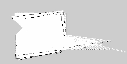
Edit: I found the real problem: Your scanner reports a field of view of 270 degrees and an angle increment of 0.5 degrees (like you mentioned). So you would expect about 540 rays per scan. But in reality there are 1081 readings in each message! So gmapping tries matching a 540 degrees field of view... There must be something wrong with your laser driver. The first 540 readings are correct, but there are another 540 zero-readings in each laserscan message.

edit flag offensive delete link more

Comments

Sorry, I didn't quite catch ya. I m using SICK LMS100 laser range finder, with 270 degree laser coverage and resolution of 0.5 degree. I checked the laser dots shown in the rviz, they fit the environment quite well after I turn the scanner frame 90 degree clockwise about the z-axis.

Kent gravatar image Kent  ( 2013-01-14 04:10:32 -0500 )edit

Yes, thats because your scanner returns this values in the message: "angle_min: -0.785398185253 angle_max: 3.92699074745" But GMapping assumes that a laser scan is centered around the x-axis of the laser-frame. Thats why its messed up. Could you post your sick-driver launch file?

Ben_S gravatar image Ben_S  ( 2013-01-14 05:12:40 -0500 )edit

Thanks. But the x axis of the laser frame coincides with the 0 degree. Should I modify the laser driver code? Or is there any short-cuts?

Kent gravatar image Kent  ( 2013-01-14 05:21:27 -0500 )edit

my launch file is like this:<node pkg="LMS1xx" type="LMS100" name="LMS100" output="screen"> <param name="host" value="192.168.1.105"/> <param name="frame_id" value="base_laser"/> </node>

Kent gravatar image Kent  ( 2013-01-14 05:23:13 -0500 )edit
1

I found the real problem: Your scanner reports a field of view of 270 degrees and an angle increment of 0.5 degrees (like you mentioned). But in reality there are 1081 readings in each message! So gmapping tries matching a 540 degrees field of view...

Ben_S gravatar image Ben_S  ( 2013-01-14 05:24:27 -0500 )edit

U mean that the laser driver publish 1081 laser data (with correct laser data and a lot of zeros in it)in each msg? But I've also tried using this laser driver in hector mapping, everythings seemed fine

Kent gravatar image Kent  ( 2013-01-14 05:34:38 -0500 )edit

GMapping is a little messy with the angles. The underlying routines dont know anything about min- and max-angles. They calculate them solely by the number of readings and the reported angle increment. This isnt very robust... (And it assumes the centered scans like i already mentioned)

Ben_S gravatar image Ben_S  ( 2013-01-14 05:48:03 -0500 )edit

So the x axis of the laser frame should coincides with the x axis of the base frame, the laser data should starts at 90 degree, and the number of the laser data should be fixed by delete that redundant zeros?

Kent gravatar image Kent  ( 2013-01-14 06:00:02 -0500 )edit
0

answered 2013-03-27 15:16:22 -0500

elva gravatar image

Hi,Kent,i am doing 2D hector mapping,i have the same problem as the picture you posted.but your map with hector mapping was good,may i know how you did it ,especially the tf tree.btw, i have a hokuyo URG-04LX and mircostrain 3DM-GX3-25 imu,thank you in advance^^

edit flag offensive delete link more

Comments

I do not have any experiences in using the imu with hector mapping, whatever, hector mapping can be utilized without odometry but with laser data only. U may check http://www.ros.org/wiki/hector_slam/Tutorials.

Kent gravatar image Kent  ( 2013-03-27 15:37:05 -0500 )edit

i have followed the setup, using the second one" Use without odom frame",however even i only use hokuyo node and hector_mapping node,and a tf name="base_to_laser_broadcaster" ,but the map overlaps,in a mess:( do you use any other node?thanks

elva gravatar image elva  ( 2013-03-27 16:14:03 -0500 )edit

I do not use other node. If u use hector mapping without odometry, the tf should be like this: laser_frame->base_frame. Better checking the tf and the laser scan data to see if they are correct.

Kent gravatar image Kent  ( 2013-03-27 16:27:26 -0500 )edit

the reason why my mapping overlaps is that the laser scan does not match, but i know hector mapping no need laser scan match node right? is there any way to solve it ?really appreciate you reply^^thank you.And my email is : elva2011@hotmail.sg, hope to hear from you by email:)

elva gravatar image elva  ( 2013-03-27 17:18:25 -0500 )edit

hi elva and kent, i am having the same problem using the hector slam with rplidar, the map gets overlapped.... help me out with this i will be really grateful to you both. thank you :)

hashim gravatar image hashim  ( 2015-09-06 14:20:17 -0500 )edit

Hi,hashim. Can you give more details about your problem so that I can help you.

Kent gravatar image Kent  ( 2015-09-09 04:24:08 -0500 )edit

the problem i am facing is as long as i do not give yaw, pitch and roll motion to the lidar, the map is good but when i give these motions the map starts to overlap.... someone has told me to use the IMU with Lidar but i dnt know how to incorporate IMU data into Lidar. is there any solution ??

hashim gravatar image hashim  ( 2015-09-09 14:00:19 -0500 )edit

but if i change my fixed frame to scanmatcher_frame, the map is very little affected by these yaw, pitch and roll motions but nonetheless it does.. i want to know why ??

hashim gravatar image hashim  ( 2015-09-09 14:02:23 -0500 )edit

Question Tools

3 followers

Stats

Asked: 2013-01-13 17:06:15 -0500

Seen: 4,016 times

Last updated: Mar 27 '13