
UR5 how to convert axis angles to quaternions
Hi,
We have a UR5 robotic arm. We use Moveit move_group_interface to send simple pose and joint-space goals to this arm. In particular for the pose message of the type,
geometry_msgs::Pose pose_msg;
the position component is reached correctly. But, I cannot correctly find the orientation component. In UR5, what we read on PolyScope is axis-angle representation given as a rotation vector [rx, ry, rz]. But, for ROS side, we need quaternion representation. I have followed some help online, but still cannot get the right orientation of the tool point. For example, this suggested an approach, which I have followed,
  std::vector<double> axis_angles{ang_a, ang_b, ang_c};  // as read on the polyscope
  double theta = GetNorm(axis_angles);     // sqrt(ang_a² + ang_b² + ang_c²)

  double ux, uy, uz;

  ux = ang_a/theta;
  uy = ang_b/theta;
  uz = ang_c/theta;

  tf::Vector3 unit_vector(ux, uy, uz);
 tf::Quaternion quat;
tf::Quaternion quat_inv(tfScalar(-0.5),tfScalar(0.5),tfScalar(-0.5),tfScalar(-0.5));
quat.setRotation(unit_vector,theta);
quat *= quat_inv;

pose_msg.orientation.x = quat.getX();
  pose_msg.orientation.y = quat.getY();
  pose_msg.orientation.z = quat.getZ();
  pose_msg.orientation.w = quat.getW();
However, the final orientation of the last link is inverted (facing up). I would like it to be so that its perpendicular to a table surface below (facing down), so that an attached gripper can pick things from the table.
I also tried the following
tf2::Vector3 axis(ux, uy, uz);
  tf2::Quaternion Quat(axis, theta);
Still cannot get the the orientation to what I encode in the pose message.
How can I correctly specify in ROS the orientation for a UR robotic arm given the axis angles.
*EDIT
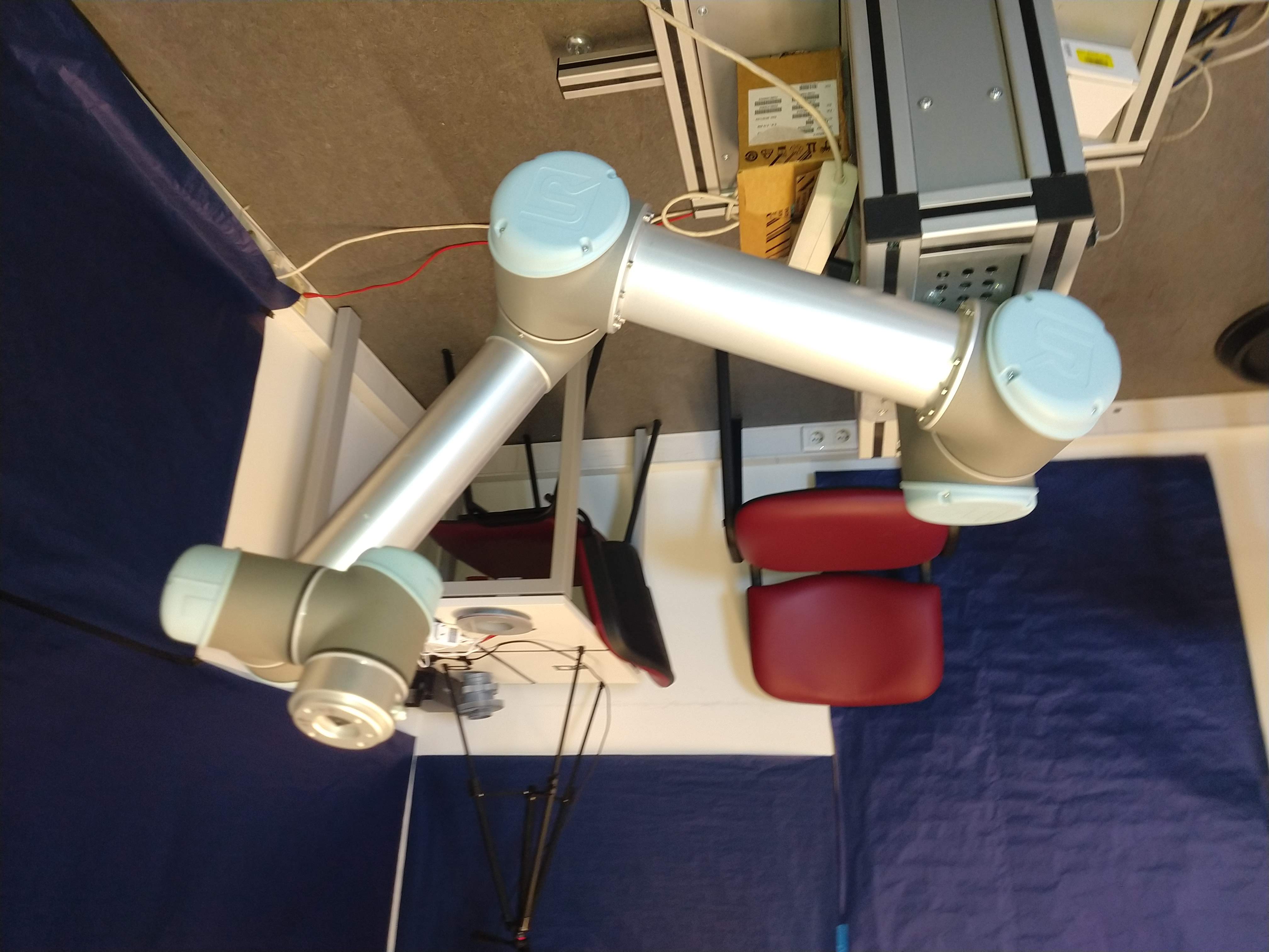
So following the suggestions given by @fvd, I have made test on UR5 robotic arm. I attach the picture from three cases below.
(a) Using the method above that I described, but discarding the quat *= quat_inv; part.
In a few tests performed, I could not see valid motions, and usually the motion of stopped due to the arm violating some safety boundary set on the teach pendant.
(b) Using the method above, and keeping quat *= quat_inv; part.
teach pendant reads.
X = 138.28
Y = -539.49
Z = 394.44
RX = 1.9577
RY = -2.5844
RZ = -0.0577
(c) Applying the approach that was suggested by @fvd 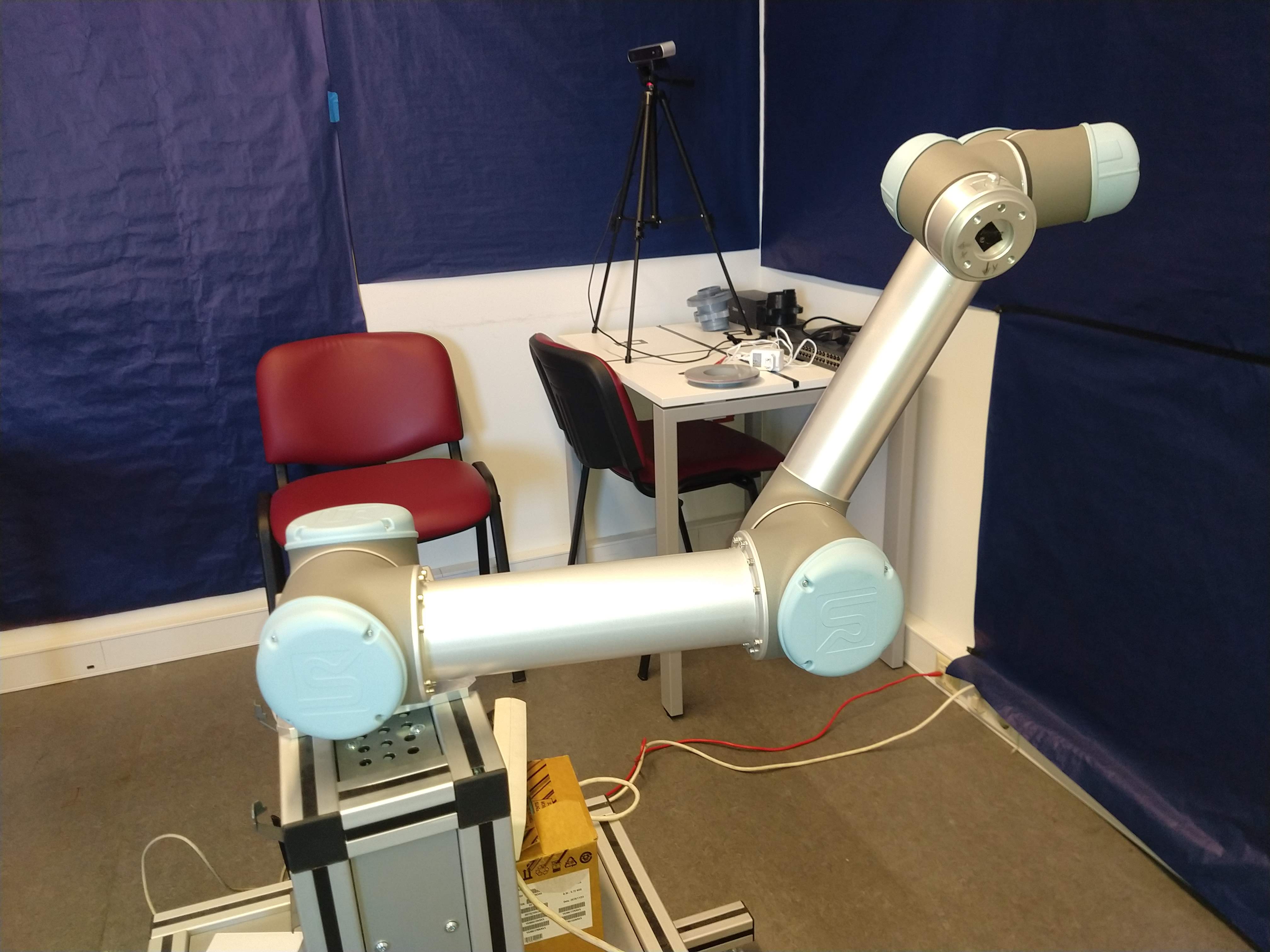
teach pendant reads.
X = 137.80
Y = -548.39
Z = 391.40
RX = 0.3176
RY = -3.3345
RZ = -2.7655
This was the pose string that was given to the motion planner.
std::string s = "[-0.14527758743934377, 0.5449976892506504, 0.38858309510149047, -0.15787628477528537, 0.2747166458598104, 0.5450830459979051]";
(Note that, x and y coordinates of the pose are opposite signs between ROS MoveIt and teach pendant, in ROS the values are given in radians, and in meters, wheres on teach pendant, the x, y, z of the pose are given in millimeters. )
thanks, Zahid

Sorry, I can't get into the details right now. I suggest that you use a package like rviz_visual_tools to publish Coordinate System markers to visualize different orientations in Rviz and debug the different methods. Planning with the robot can fail for unrelated reasons. You should check if the results for your orientations are consistent, not if a motion plan can be found.
I'd guess this is an issue with frames. Viewing the link you posted, it looks like the base frame has X pointing back, Y pointing right, and Z pointing up. The
quat_invyou showed above is meant to adjust these frames so that X points down and Z pointing right, which may not be right for you. I'd play with those values.I need to pick up an object with the UR3 manipulator. But the orientation I get from the object view in the workspace has the Z-axis coordinate reversed. I guess this boils down to mirroring around the XY plane. To mirror a quaternion around the XY plane, I think you need to negate the Z value and the W value. Can you confirm? Except that when I negate the values the result is not correct. But if I add to Roll pi I already have the valid value. Only this is not a good solution. How can I invert the Z of the object to be coincident with the Z of the gripper?
hi @RB_Code, I was having the same issue. the final orientation is reversed (upside down Z). I could not get it to work, The workaround that we did (and, this is not a proper solution), was to firstly, take the robotic arm to home position, where the gripper is perpendicular to the ground. This "home" position is a named target. And, then for reaching the goal target pose, I just copy the orientation from this "home" position to the orientation part of the target pose. Please update, if you get any final working solution. thanks,