
Lidar scan detected obstacle not reflected in Costmap

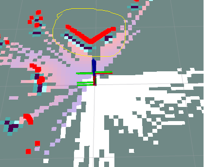
I am using an RPLidar A1 as my lidar scan. There is a square box right in front of my robot. The lidar scan detects the box contour correctly and you can see that in rviz image below. However, the occupancy grid does not reflect what is being provide by lidar scan. I have tried multiple units of RPlidar A1 and switched the micro-usb cable. The result is the same:
The occupancy grid in front of the robot at a 15-30 degree angle, does not reflect the lidar scan. However, if I flip the robot, i.e facing away from the box, the grid is updated perfectly.
Given that the grid updates perfectly everywhere else, I believe the issue is not with my configuration. I have used the rviz select tool to check the intensity of the scan in the area where the costmap is not updated. The intensity is the same as the areas where the costmap is updated with the obstacle.
Both my global and local costmap param settings look like this:
  update_frequency: 5.0 (20 for local)

  publish_frequency: 5.0 (20 for local)

  global_frame: map

  robot_base_frame: base_link

  footprint: "[[0.19, 0.09], [0.19, -0.09], [-0.05, -0.09], [-0.05, 0.09]]"

  footprint_padding: 0.10

  resolution: 0.05

  lethal_cost_threshold: 200

  track_unknown_space: true

  plugins: ["static_layer", "obstacle_layer", "inflation_layer"]

  static_layer:

    plugin: "nav2_costmap_2d::StaticLayer"

    map_subscribe_transient_local: True

  inflation_layer:

    plugin: "nav2_costmap_2d::InflationLayer"

    cost_scaling_factor: 10.0

    inflation_radius: 0.15

  obstacle_layer:

    plugin: "nav2_costmap_2d::ObstacleLayer"

    enabled: True

    max_obstacle_height: 0.4

    observation_sources: scan

    scan:

      topic: /scan

      clearing: True

      marking: True

      data_type: "LaserScan"

  always_send_full_costmap: True
I am perplexed as to what can cause this. The scan is doing it's job correctly. The costmap is updated correctly everywhere except the dead zone.
Can someone please help me resolve this mystery?

Some clarifying questions:
/scantopic is publishing data that matches your expectation (e.g. if you only visualize/scanand not the costmaps?The image included is before I flip the robot. Yes. /scan is publishing data that matches my expectation. I moved the robot closer to the object and saw that the gap reduced in size. There is nothing in front of the robot that is blocking the scanner.
I did an echo on the scan topic yesterday and realized the following for RPLidar A1: angle_max = 3.1415 = 180 degrees angle_min = -3.1241 = -179 degrees
There seems to be a 1 degree blind spot. And this blind spot can create larger gaps, the further the robot is away from the obstacle. Would you agree with my suspicion that this indeed looks the cause of the issue?
If I'm not mistaken, the 1 degree "gap" is intentional and correct; the RPLidar scans in 1 degree increments. Scanning from -179 to 180 deg avoids "double-covering" of the -180/180deg point.
Going off your image, it is hard to see what is "wrong". Assuming the
/scanis visualized in red, the cost map would seem to be appropriately (albeit with a small gap) representing the obstacle (blue and black near the scan). What looks like the map from slam_toolbox (the gray vs white occupancy map) is maybe what you're asking about? But that too doesn't seem too abnormal to me. The demo gif here shows a similar behavior, and the free space is only updated on the map after the robot moves through it a bit. I haven't looked in too much depth at what goes on under the hood, but I'd imagine its quite tied to feature persistence and agreement with odometry. My recommendation would be to drive the robot around and see if the map gets updated accordingly.But if that's not what you ...(more)
The small gap in the costmap is the issue I am trying to address. Is that always to be expected? If so, why? Why does the /scan output look proper but that specific area on the costmap in front and to the right of robot not reflecting the scan input?
ahhh I see - thanks for clarifying. if the scan intensities are all the same, I am out of ideas for now... I added the
nav2tag to your question to see if someone more involved with the project can offer some feedback