ROS Resources: Documentation | Support | Discussion Forum | Index | Service Status | ros @ Robotics Stack Exchange
Ask Your Question
0

Incorrect Bounding Boxes using pcap file with 3D Perception Stack of Autoware.Auto

asked 2021-02-22 14:43:43 -0500

joshuakurien gravatar image

updated 2021-02-23 09:18:43 -0500

Hi, I have been trying to run the 3D perception stack demo (https://autowarefoundation.gitlab.io/...), but seem to be getting incorrect bounding boxes (see video below). The demo ran in an ade environment using the .aderc-amd64-foxy file. There seems to be a similar issue here, but in my case I am not using the LGSVL simulator. To run the demo the following commands were done:

Terminal 1:

ade$ udpreplay -r -1 route_small_loop_rw.pcap

Terminal 2:

ade$ source /opt/AutowareAuto/setup.bash
ade$ ros2 run velodyne_nodes velodyne_cloud_node_exe --model vlp16 --ros-args --remap __ns:=/lidar_front --params-file /opt/AutowareAuto/share/velodyne_nodes/param/vlp16_test.param.yaml

Terminal 3:

source /opt/AutowareAuto/setup.bash

Terminal 4:

ade$ source/opt/AutowareAuto/setup.bash 
ade$ ros2 launch autoware_demos lidar_bounding_boxes_pcap.launch.py

This is my current rviz visualization: https://youtu.be/ANKaX4vJIFE. The bounding boxes seem to be incorrect and I am not too sure why. Any input would greatly be appreciated. Thank you.

edit retag flag offensive close merge delete

Comments

Can you be more specific? What do you mean by "seem to be incorrect?" Maybe a screenshot would help.

Josh Whitley gravatar image Josh Whitley  ( 2021-02-23 08:36:16 -0500 )edit

Yes, sorry about that. Here is a video of my visualization currently https://youtu.be/ANKaX4vJIFE.

joshuakurien gravatar image joshuakurien  ( 2021-02-23 09:20:37 -0500 )edit

Playing back route_small_loop_rw.pcap does show the roads being detected as non-ground objects and thus explains the euclidean clustering algorithm creating a bounding box for it.

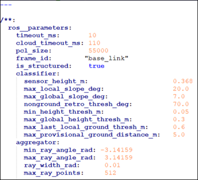
The question is, are the parameters for the 3D perception stack set according the appropriate location and orientation of the sensors when the route_small_loop_rw.pcap file was captured? If yes, then what is the explanation for the roads being detected as non-ground objects? If no, then is there another pcap file that could be used to test the perception stack with the current parameters values?

Also, I noticed the orientation of the rear lidar is reversed and it had to be rotated 180 degrees by changing the quaternion in /opt/AutowareAuto/share/point_cloud_filter_transform_nodes/param/vlp16_sim_lexus_filter_transform.param.yaml when testing with the provided file, route_small_loop_rw.pcap.

asobhy-qnx gravatar image asobhy-qnx  ( 2021-03-18 08:36:47 -0500 )edit

1 Answer

Sort by ยป oldest newest most voted
1

answered 2021-02-23 17:27:30 -0500

shlokgoel gravatar image

I think the problem has something to do with the ray ground classifier node. This node is responsible for segregating the filtered point cloud (output of Point Cloud Filter node) into ground and non-ground objects. From the visualization video you referenced, it seems that in your case, the ray-ground classifier node is classifying the entire plane as non-ground. Hence, the euclidean cluster node (which is responsible for clustering and generating bounding boxes) is creating bounding boxes that cover your entire plane.

In order to fix this, I would recommend changing the parameters of the config file for the Ray Ground Classifier Node which can be found here: /opt/AutowareAuto/share/ray_ground_classifier_nodes/param

The config. (param) file used in the demo is called vlp16_sim_lexus_ray_ground.param.yaml

The content of the param file are as follows:

image description

Here you would want to modify the sensor_height_m parameter to get the right results. One thing to keep in mind is that you might have to build the autoware.auto repository for the changes to take place.

Hope this resolves your isse!

edit flag offensive delete link more

Comments

Hi shlokgoel,

Thanks for the suggestion. This did help improve the visualization, but it still needs some more improvement.

joshuakurien gravatar image joshuakurien  ( 2021-02-25 08:32:23 -0500 )edit

You might want to modify the param (.yaml) file for the Point Cloud Filter node as well. That file contains the static transformer (x,y, and z) and that might help you make the visualization better. Also, if you think the answer was satisfactory, you can mark my answer as correct (by pressing the tick mark next to the answer)

shlokgoel gravatar image shlokgoel  ( 2021-02-25 08:40:06 -0500 )edit

I will try that as well, thanks. I am still seeing if there are other ways to improve the object detection.

joshuakurien gravatar image joshuakurien  ( 2021-03-02 08:29:34 -0500 )edit

Why would those parameters have to be changed if he is running the pcap file that was captured using the same settings?

asobhy-qnx gravatar image asobhy-qnx  ( 2021-03-16 11:30:45 -0500 )edit

Question Tools

Stats

Asked: 2021-02-22 14:41:56 -0500

Seen: 298 times

Last updated: Mar 18 '21