
weird initial path from robot_localization's EKF node
Hi all,
I am trying to evaluate our EKF fused odom_IMU_DVL performance based on odom_reference that EKF fused by differential GPS and other sensors(IMU...). The odom_IMU_DVL is fused with IMU(madgwick filtered) and DVL(measured underwater vehicle velocity).
Performance:
I have a rosbag included online recorded odom_reference and raw data to do offline EKF for odom_IMU_DVL. In order to align both path for analysis, I set an initial state obtained from odom_reference. There are two issues stop alignment.
- wired initial path
- about 10 degree yaw difference at beginning
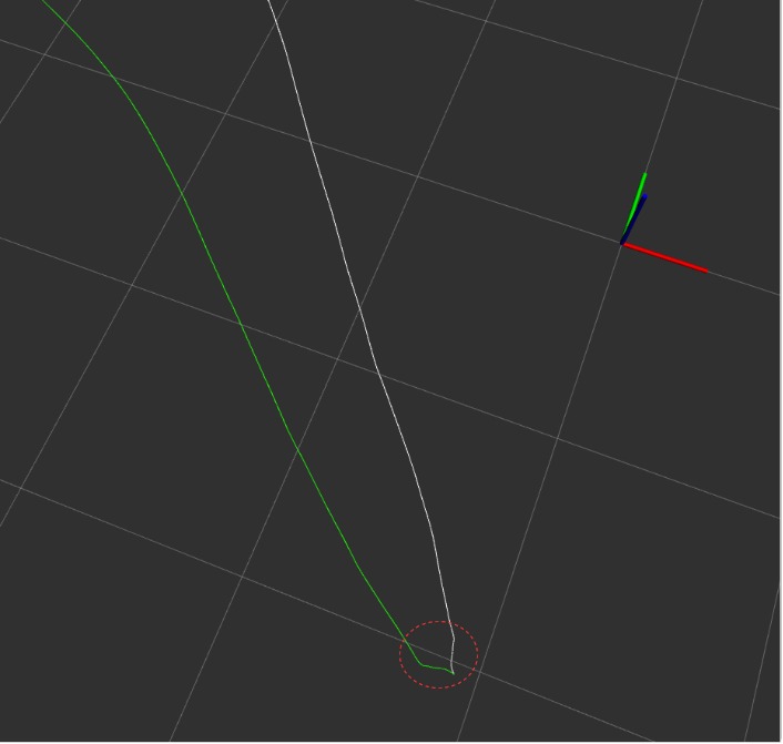
This is the path at beginning, green is odom_reference and white is odom_IMU_DVL. We can see there are wired path shown in red dotted circle. The reason I said wire because both of the path should be straight not curved, at least not curved like that.
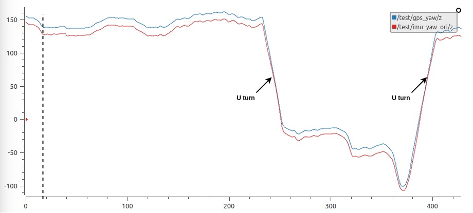
There is the yaw comparison. Blue is odom_reference, red is odom_IMU_DVL. There are about 10 degree at the beginning. The first range cut by black dotted line is the yaw angle for wired initial path. 10 degree yaw difference at beginning is make sense, the heading of odom_IMU_DVL is not accurate as odom_reference.

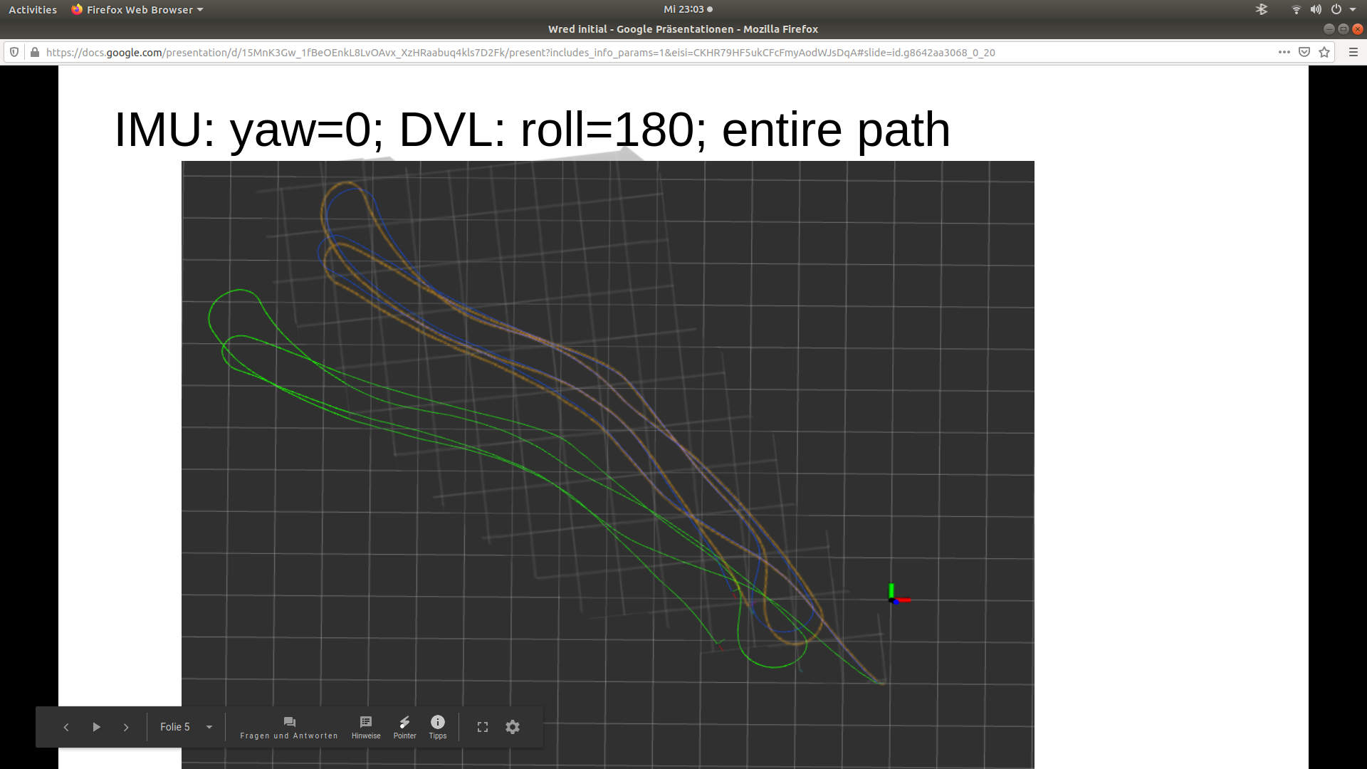
This is the entire path according to previous yaw angle plot.
My questions:
- The wired initial path is EKF initialization problem, which is can't avoid ?
- The initial 10 degree yaw difference is normal because different heading accuracy ?
- If those are normal, can I compensate odom_IMU_DVL by giving a GPS heading at first beginning like the method as initial_state in robot_localization?
- If those are normal, can I manually compensate those two error in order to evaluate the entire path by giving a static transformation just at the beginning? Because those error seems should not account for the overall drift.
The EKF config file for your information. Thanks for your help.
--------------------------------------------------------------------------------
UPDATES !!!!!
Thanks to Dragonslayer's suggestions, the wired initial path caused by wrong static tf setting between sensors frame and base_link.
So the only problem I have right now is:
- a large initial angle between odom_IMU_DVL and odom_reference, which is about 99 degree.
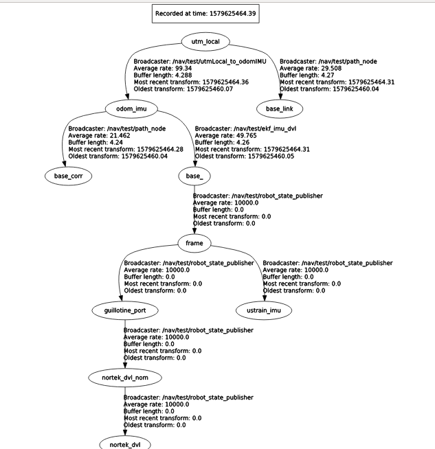
This is the tf:
- odom_reference related: utm_local is the parent frame; base_link is the base frame;
- odom_IMU_DVL related: odom_imu is the odom frame assigned in EKF; base_ is the base frame; ustrain_imu is the IMU frame; nortek_dvl is the DVL frame. I set 0 static tf (it's in launch file, not in urdf since it's not related to EKF) between odom_imu and utm_local, so that two path are displayed together.
- forget about base_corr: this is a path I displayed a 99 degree rotation to manually fix this issue.
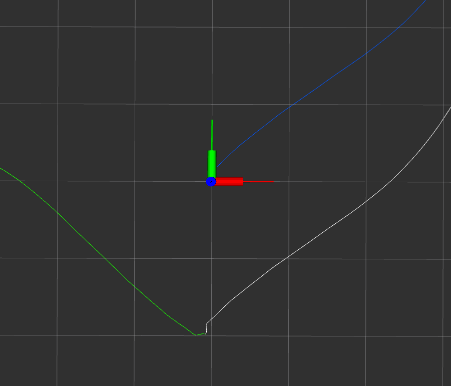
This is the initial plot: about 90 degree between two path, and it's about rotate 90 degree to whole path. The giant frame in the middle is the utm_local; the slim frame in the center is odom_imu. The blue path is actual path without assign inital_state.
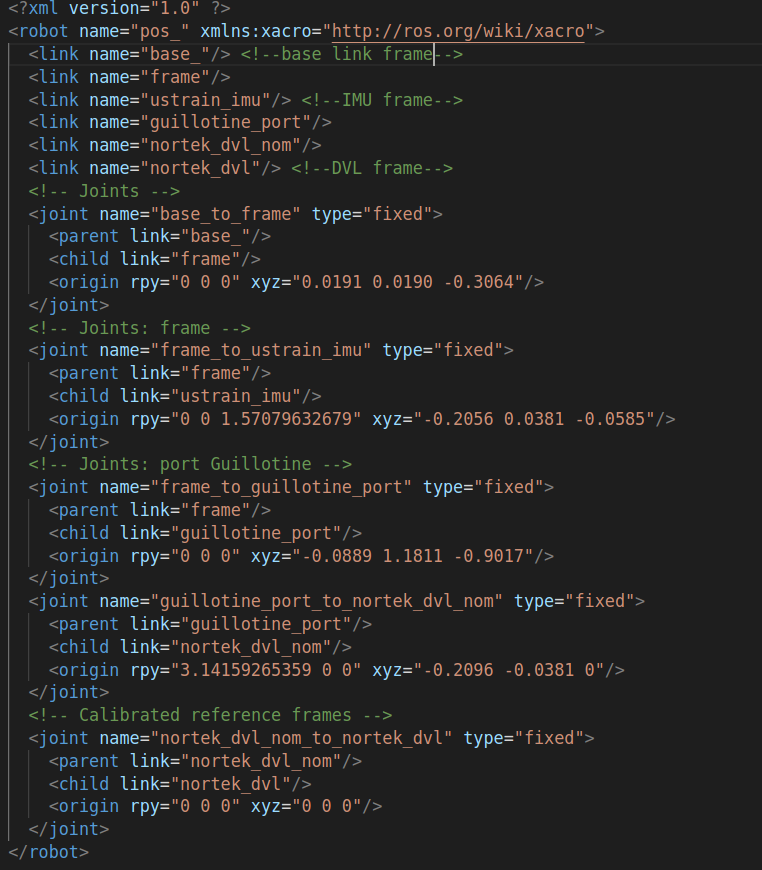
urdf: it's kind complicated based on real setup in boat. just check base link frame, IMU frame and DVL frame.

Hi, I cant open your EKF config file. What do the ekf inputs look like? EKF doesnt need an initial_pose as it starts at Zero, its localization that gives the map-->odom transform to place the odom frame in the maps initial position. How "large" is this path, are the squares meters wide? What kind of velocities are we talking here, how long does it take to complete the movement? Are those 400 seconds in the graph?
Hi, thanks for your reply. the config file is accessible right now.
I know EKF does not need initial_pose, the reason I used because I want align both path together at the beginning for pose error analysis. Because the odom_reference is a differential GPS fused odometry, it's actual starting point always have an actual gap to the parents frame. For my odom_IMU_DVL EKF, I just use odom->base_link for tf, I think usually map->odom is used for GPS data fusion. And I use static_tf to align odom_reference's parent frame with odom_IMU_DVL's parent frame, which is odom. That's why I used initial_pose.
odom_reference is just from rosbag and consider as ground truth, which is done by my colleague. Those just 400 step in the graph, each step is a EKF step I think. In the rviz, each cell is about 25 meter.
EKF step? The config file shows frequency 50 that means 8 seconds (400) and the cell widht is 25 meters, averadge ~85 m/s. Rviz seem to shows reference -yaw for the reference but +yaw for odom..., the graphs show both -yaw. They are not diverging by the data. Maybe what we see is really a z movement, you start with -0.018 roll at an acceleration z of nearly 10 m/s. rviz is 3d. gps is 2d. So maybe we see odom frame coming towards the camera at an angle and not really going sideways (perspective). At 10 m/s and a delayed imu/odom update odom skyrockets towards the camera. Maybe test with initial_state velocities and accelerations at Zero.
By the way, regarding the 10 degree offset, might the gps give true north while the imu gets magnetic north? Or somehow one interprets it as one or the other?
I am sorry, I double checked the time axis in plot. The 400 step is about 14s. The yaw angle all processed in callbacks directly from EKF odom. The odom are 50 hz, but the yaw angle published in about 28 hz. That's wired. Because the processing is simple and should be published as 50 hz, but it's not. We are collecting data in a pontoon boat driving by people. By calculating based on gps path in rviz, the vehicle velocity is about 2~3 m/s, that's reasonable.
for the 10 degree offset, I think your are right, the vehicle is metal and is huge. We didn't calibrate the mag in 3D space and just drive the vehicle A big 8 for mag calibration. And the heading is mainly from mag, so that's the error we are hoping. The main question I have is the wired path at the beginning. Also, I tried without initial_state, the wired path still there.
As the "path error" is not there in the data graph, it might just be a rendering bug or something like that in rviz. The data graph definitly doesnt show divergence of the two starting points, just the initial error. Also if you are moving in 2d space I would try to get rid of all pitch roll and z components and try again. The covariances might "go crazy" (lose precission due to unrelated movement taken into consideration that have nothing to do with the relevant 2d movement) specially as the boat is likely riding uneven (waves). Could you post graphs comparisons of the x and y positions, might be helpful?
Is the IMU a Bno055? There is a setting to get yaw without the usage of mag, only gyros and acceleratometers.