ROS Resources: Documentation | Support | Discussion Forum | Index | Service Status | ros @ Robotics Stack Exchange
Ask Your Question
1

robot_localization - angular drift when fusing IMU

asked 2020-01-13 07:23:15 -0500

updated 2020-01-29 03:57:53 -0500

I've run into an interesting issue. It seems that when I'm fusing angular velocity it ends up adding a significant angular drift to odometry output.

My robot platform is a differential_drive robot with a caster wheel. On my robot I have two IMUs: one in the front (Realsense Tracking camera) and another one in the back (Phidgets Spatial IMU).

Here is my starting robot_localization config:

odom_frame: odom
base_link_frame: base_link
world_frame: odom
publish_tf: true
frequency: 25

two_d_mode: true

odom0: /rr_robot/mobile_base_controller/odom
odom0_config: [false, false, false,
               false, false, false,
               true, true, false,
               false, false, false,
               false, false, false]
odom0_differential: false

# imu0: /rs_t265/imu
imu0: /imu/data_raw
imu0_config: [false, false, false,
              false, false, false,
              false, false, false,
              true, true, true,
              false, false, false]

imu0_differential: false
imu0_relative: true

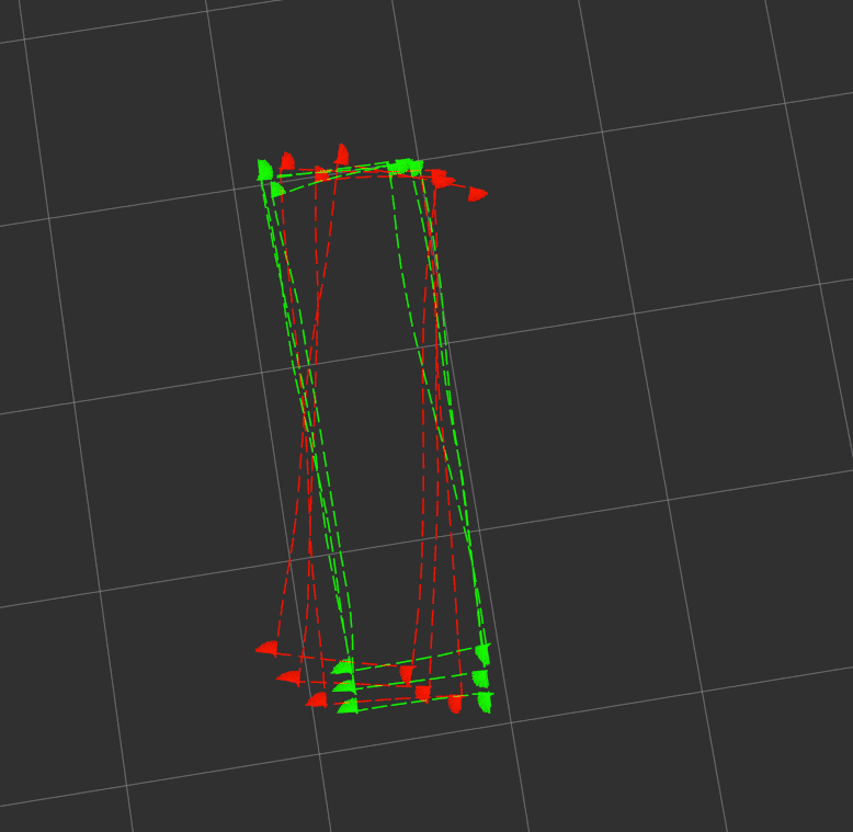
Here is the output for the /rs_t265/imu topic (mounted in front): image description

and here is the output when using Phidgets (mounted in the back of the robot): image description

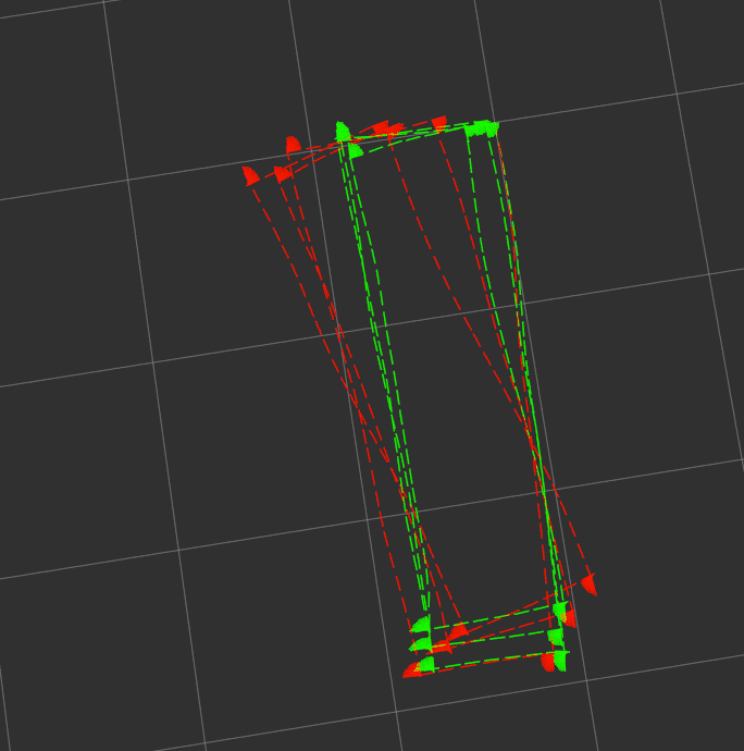
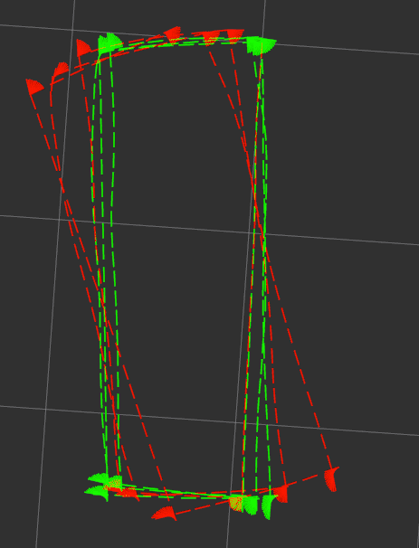
The green odometry in the picture is the wheel odometry that is very close to the actual path traveled by the robot. The odometry marked in red is the output of robot_localization package.

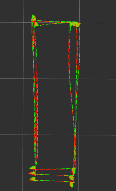
Almost all sources I've seen on the internet suggest fusing x and y velocity from the odometry topic and angular velocities of the IMU (magnetometer doesn't work well enough for me due to magnetic interference). The only way I can get the fused odometry appear much closer to the wheel odometry is by fusing the yaw of odom0 message, however it seems to make the filter not take the imu into account very much:

image description

Am I'm missing something in my setup? I think I read up all the information on robot_localization that's available on the internet and didn't come to any obvious conclusions. I'd appreciate any feedback you might have!

EDIT: Some additional information: For each of the IMU setups the sensor frame seems to be correctly specified in the TF tree and is correctly contained in the appropriate IMU message fields.

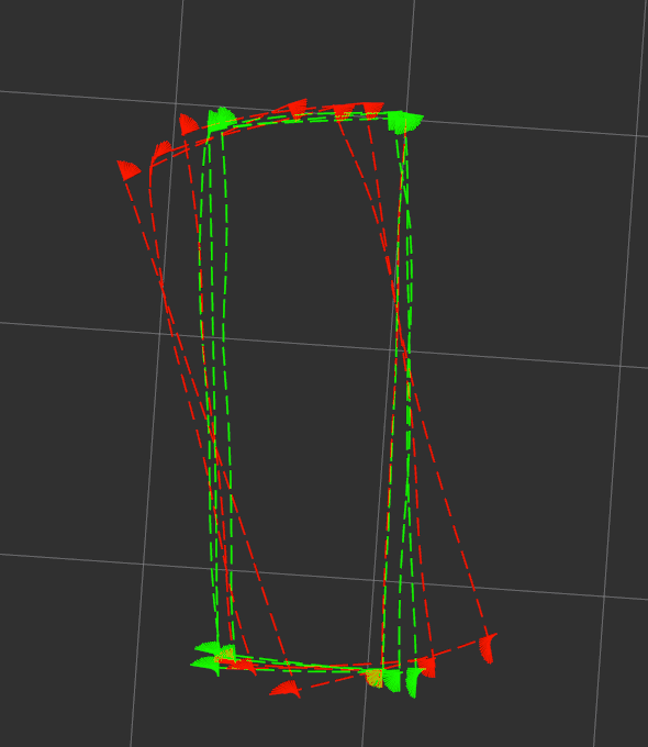
EDIT2: Output when using madgwick filter to produce an IMU message with orientation field and fusing the resultant yaw looks as follows: image description

Unfortunately in 3 of the 4 corners I turn at there are huge metallic object affecting the magnetometer.

EDIT3: Trying to fuse yaw rate from wheel odom.

Before yaw rate fusion: image description

After fusing yaw rate: image description

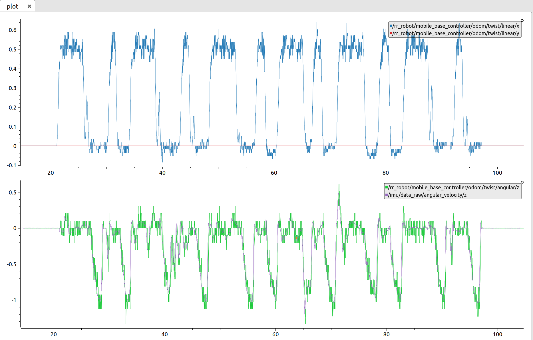
When I said that my platform used encoders I lied a bit - actually I only have data from the motor's hall sensors. This makes the data quite noisy, below you can see a graph with wheel odom velocity on x and y and yaw rates (from wheel odom (green) and imu (purple). Would this noise contribute to my issue?

image description

EDIT4: Sample sensor input:

Wheel odometry(/rr_robot/mobile_base_controller/odom):

header:
  seq: 2443
  stamp:
    secs: 1579080868
    nsecs: 941759306
  frame_id: "odom"
child_frame_id: "base_link"
pose:
  pose:
    position:
      x: 2.38348355885
      y: 0.0650385644131
      z: 0.0
    orientation:
      x: 0.0
      y: 0.0
      z: -0.502680731125
      w: 0.864472140994
  covariance: [0 ...
(more)
edit retag flag offensive close merge delete

Comments

Do any of the IMUs give you out the orientation? I'd use that over others. You may want to try putting one of the IMUs through a complementary filter and then the output orientation into R_L.

stevemacenski gravatar image stevemacenski  ( 2020-01-13 14:51:13 -0500 )edit

One of the IMUs gives out orientation, however, the environment I run the robot in contains huge metallic object near 3 of the corners I turn at. I'll edit the question to add the visualisation of this one. It's actually using Madgwick and should fuse magnetometer with other sensors.

msadowski gravatar image msadowski  ( 2020-01-14 04:54:08 -0500 )edit

Are you _sure_ all the sensors are being fused? I presume you are using a bag file to get repeatable results; how are you modifying the covariance values in your bag file? Did you define static transforms for the IMU data frame_ids? And are you plotting the right output topic? The fact that _nothing_ changes the output leads me to believe one of the inputs is being ignored. What happens if you turn off the IMU input?

Tom Moore gravatar image Tom Moore  ( 2020-01-28 05:26:07 -0500 )edit
  • I've updated the question to show the output with imu config commented out
    • I use only joint state information from the bag file and run differential_drive controller with this data, by changing the config I can modify the covariance
    • I've checked the time in all messages and it's consistent
    • All static transforms are there and the tree seems OK (checked with rqt_tf_tree and also with roswtf)
    • I checked rosnode info with ekf node and rqt_graph and can confirm that both imu and odom topics are fed into the ekf node. I also confirmed that I'm subscribed to the correct topic (odometry/filtered)
msadowski gravatar image msadowski  ( 2020-01-28 07:09:58 -0500 )edit

So the filter is clearly trusting your IMU far more than your odom data. At this point, I would turn on debug mode (set the debug output file to an absolute path), let the robot go through a single turn, then quickly kill it. Zip that and post it here.

Tom Moore gravatar image Tom Moore  ( 2020-01-29 03:40:41 -0500 )edit

Edited the question and posted a google drive link to the zipped debug file.

msadowski gravatar image msadowski  ( 2020-01-29 03:59:34 -0500 )edit

BTW, you have two_d_mode, but are fusing roll and pitch data. Those are going to get ignored.

Tom Moore gravatar image Tom Moore  ( 2020-01-29 04:39:26 -0500 )edit

1 Answer

Sort by ยป oldest newest most voted
4

answered 2020-01-22 04:12:50 -0500

Tom Moore gravatar image

updated 2020-01-29 04:40:37 -0500

So you're fusing only velocity data. Every velocity measurement contains error. When you integrate the velocity measurements into a pose estimate, you also integrate the errors. Drift will always be an issue when you have no absolute pose data included.

But note that your wheel encoder odometry yaw is also accumulating error, before you even send it to the EKF. The robot's odometry will just be counting encoder ticks, which is also subject to error.

In any case, the root of the issue here is that your IMU is likely noisier/more biased than your wheel odometry. Try fusing yaw velocity from your wheel odometry and the IMU, and see what happens.

EDIT after question update: yeah, your covariance values for angular velocity are preventing the filter from caring about the measurements from wheel odometry. Your wheel encoders have a Z angular velocity variance of 0.03 (standard deviation of 0.173 rad/sec per measurement), whereas your imu/data_raw input is reporting an angular velocity variance of 1.2184696791468346e-07 (standard deviation of 0.0003491 rad/sec per measurement). That means you are telling the filter that your IMU is many orders of magnitude more trustworthy than your wheel odometry. You might as well not even be fusing wheel odometry yaw velocity in that case.

I'd also check your process noise covariance for yaw velocity, and make sure it's not too small, lest the filter ignore measurements because it trusts its own internal model too much (and the angular velocity model is literally just projecting the current velocity to the next timestep, so it shouldn't).

EDIT after second question update: OK, so odom fusion works by itself. My money is on sensor frequency now. What is your odometry message frequency vs. the IMU frequency? Even with equivalent covariance values, if you have 10 IMU messages for every odometry message, your odometry data will be effectively lost.

EDIT after debug file

OK, you have two problems.

First, your IMU is really off. As an example, at one of your time steps, your wheel odometry is showing an angular velocity of -0.4103, but in that same moment, the IMU is reading -0.61551. If you _just_ include IMU rotational data (turn off the angular velocity for wheel odom), I'm guessing the output would be a bit uglier.

Your process noise covariance is too high, given the noise in your sensors. What's happening is that you get an odom velocity with a tiny covariance, on the order of e-11. The filter does a predict, which adds the process noise to that quantity in its internal covariance estimate. It ends up with a covariance of something e-5. So when we do the correct step, the wheel odometry data is trusted completely, and the filter effectively jumps to the velocity in the wheel odom data. Then you get an IMU message. Again, the filter predicts across that time delta, and its internal covariance estimate moves to something ... (more)

edit flag offensive delete link more

Comments

Many thanks for your suggestion Tom. I've updated the question with some further screenshots. Fusing heading rate from the wheel odom didn't change anything and I'm wondering if it is due to the noise in my data (my platform currently is using hall sensors in the motor instead of encoders).

msadowski gravatar image msadowski  ( 2020-01-22 06:49:59 -0500 )edit

My guess is that this a covariance issues. Please post sample input messages from every sensor input. It sounds like your IMU is under-estimating its error, or that the wheel odometry is over-estimating its error.

Tom Moore gravatar image Tom Moore  ( 2020-01-24 04:04:26 -0500 )edit

Many thanks for your help! I've just edited the question and pasted the sample input of every topic I've tested my setup with. At one point I was playing with the covariance values of the wheel odometry but without too much success unfortunately.

msadowski gravatar image msadowski  ( 2020-01-24 04:27:52 -0500 )edit

Many thanks for your continued support! Weirdly none of the changes I make seem to have any effect, I've updated the original questions with some more screenshots in case you would have time to take a look at it once more.

msadowski gravatar image msadowski  ( 2020-01-28 05:29:30 -0500 )edit

The wheel odom frequency is around 50Hz, while the IMU is 62.5Hz (checked with rostopic hz while the bag was playing).

msadowski gravatar image msadowski  ( 2020-01-29 03:16:10 -0500 )edit

Many thanks for your pointers Tom, that really helps! Could the "IMU being way off" the result of high noise of my wheel odom angular twist? In my edit 3 I've posted a graph of heading rate from both wheel odom and IMU and although you can clearly see the noise in one of them it seems to follow the 'trend' quite well.

What I find odd is that I see similar behaviour (but the effects are flipped) on two different sensors (Realsense T265 and Phidgets IMU). I'll try to apply all of your recommendations and see where that gets me.

Do you think that getting proper wheel encoders could also help in this case?

msadowski gravatar image msadowski  ( 2020-01-29 06:14:47 -0500 )edit

Looking closer at the data it looks like my wheel odom angular twist has a resolution of 0.1, which doesn't sound nowhere near usable. Will try to sanitize the data before I get on with anything else.

msadowski gravatar image msadowski  ( 2020-01-29 06:15:58 -0500 )edit

The problem is that your raw wheel encoder data, as you reported, looks right: you said the robot actually traversed a rectangle (and came back to the same starting point), and when you just use wheel odometry, that's what you see. So while I agree that something is afoot, I don't know that I believe it's your encoders. Maybe try driving in a rectangle, and write a small script that integrates all the angular velocities from one IMU. When the robot returns to the start position, make it rotate to the initial heading. The summed IMU data should agree.

Tom Moore gravatar image Tom Moore  ( 2020-02-11 03:22:13 -0500 )edit

Question Tools

3 followers

Stats

Asked: 2020-01-13 07:23:15 -0500

Seen: 1,887 times

Last updated: Jan 29 '20