
Tuning PID package strange behavior
Hello everyone,
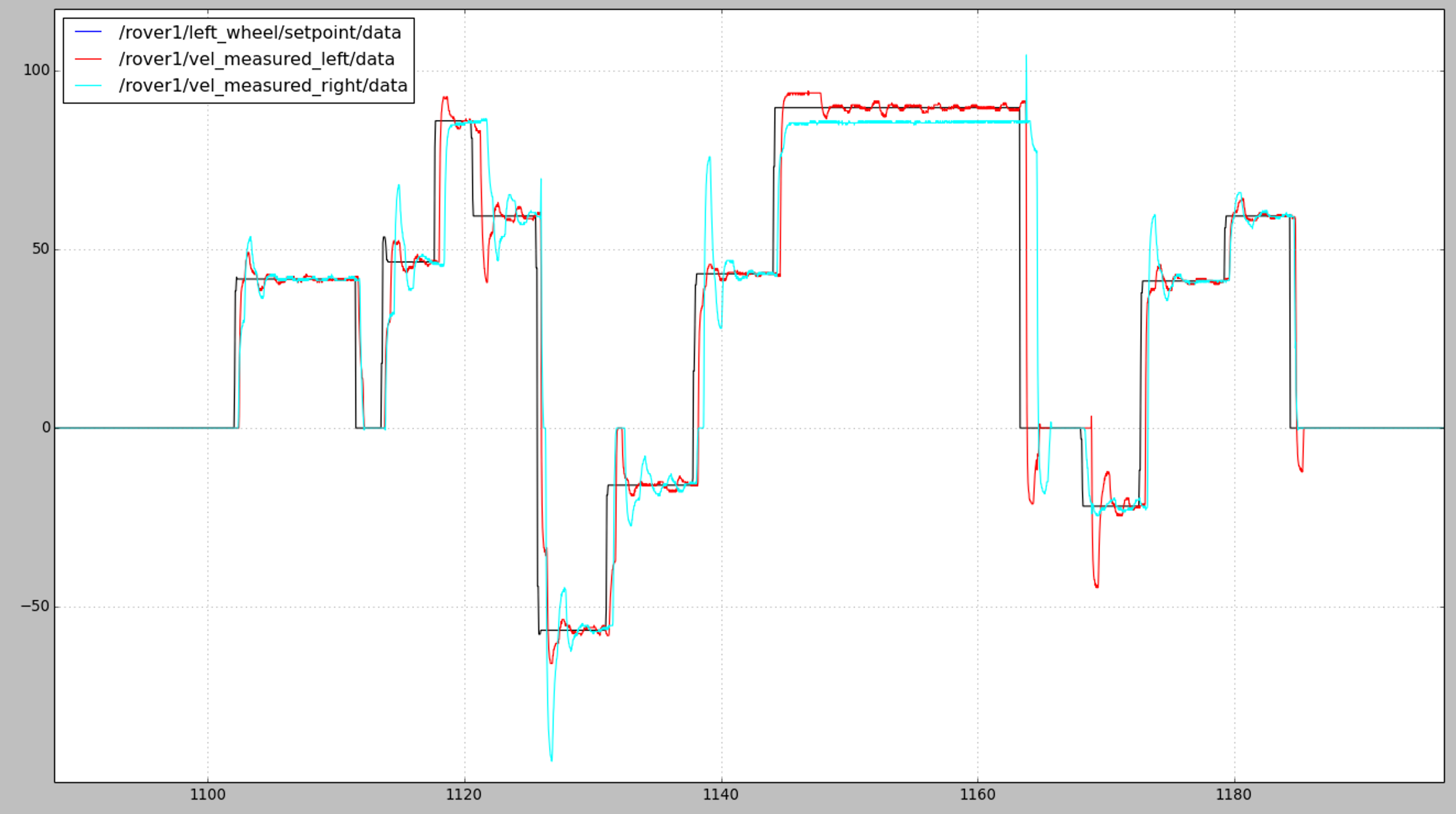
I'm working with a self made differential drive robot prototype, using ROS Kinetic. The rover is equipped with a Raspberry Pi 3 where ROS runs, an Arduino 2 to read from the encoders (hall sensor) and to control two DC motors. The bot works fine with navigation, I managed to tune a smooth pid control using ros pid package but the problem that I've encountered is that the pid starts losing the settings over time; if in the first minutes it behave smoothly and with almost zero overshooting (except some spike caused by the noisy and cheap encoders), after some time it starts to detune alone without changing any parameters. Here are three pics attached to understand better (black line is the set point for both the motors, red for the left motor and cyan for the right one):
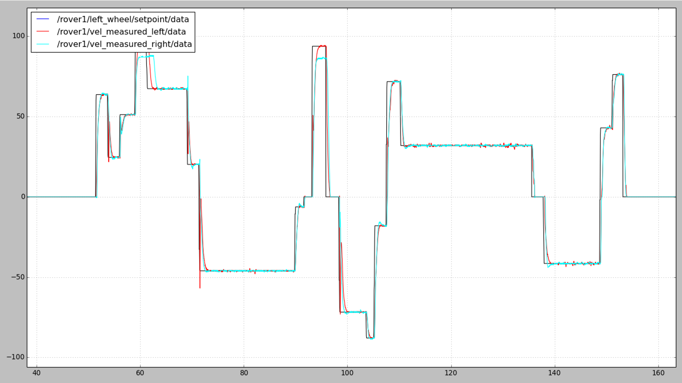 minute [0.0 to 3.0]
 minute [18.0 to 20.0]
 minute [33.0 to 35.0]
After turning off the raspberry everything works fine again but degenerate again over time. Here is the launch of the pid:
<launch>
  <node name="controller" pkg="pid" type="controller" ns="left_wheel" output="screen" >
      <param name="node_name" value="left_wheel_pid" />
      <param name="Kp" value="0.27" />
      <param name="Ki" value="2.2" />
      <param name="Kd" value="0.01" />
      <param name="upper_limit" value="70" />
      <param name="lower_limit" value="-70" />
      <param name="windup_limit" value="100" />
      <param name="max_loop_frequency" value="50.0" />
      <param name="min_loop_frequency" value="50.0" />
      <param name="setpoint_timeout" value="0.1" />
      <remap from="state" to="/rover1/vel_measured_left" />
  </node>


  <node name="controller" pkg="pid" type="controller" ns="right_wheel" output="screen" >
      <param name="node_name" value="right_wheel_pid" />
      <param name="Kp" value="0.27" />
      <param name="Ki" value="2.2" />
      <param name="Kd" value="0.01" />
      <param name="upper_limit" value="70" />
      <param name="lower_limit" value="-70" />
      <param name="windup_limit" value="100" />
      <param name="max_loop_frequency" value="50.0" />
      <param name="min_loop_frequency" value="50.0" />
      <param name="setpoint_timeout" value="0.1" />
      <remap from="state" to="/rover1/vel_measured_right" />
   </node>
</launch>
First I was thinking about some misunderstanding related to the unit of the windup limit (actually I still don't understand if it refers to time or samples), but changing the parameters hasn't varied the behavior. Instead, using 2 different values for the setpoint_timeout parameter of each motor, something changes so maybe this could be the core. I tried to set also setpoint_timeout=0 but obviously the pid doesn't work.
Are there any solution or I just have to use a brutal method like auto kill and reopen the pid node every X minutes?
Thank you for your time, any suggestions or advice is very well accepted!
EDIT 1: So as @davekroezen suggested I checked the behavior of the control_effort, as you can see in the image it starts resonating with the vel_measured around the setpoint.
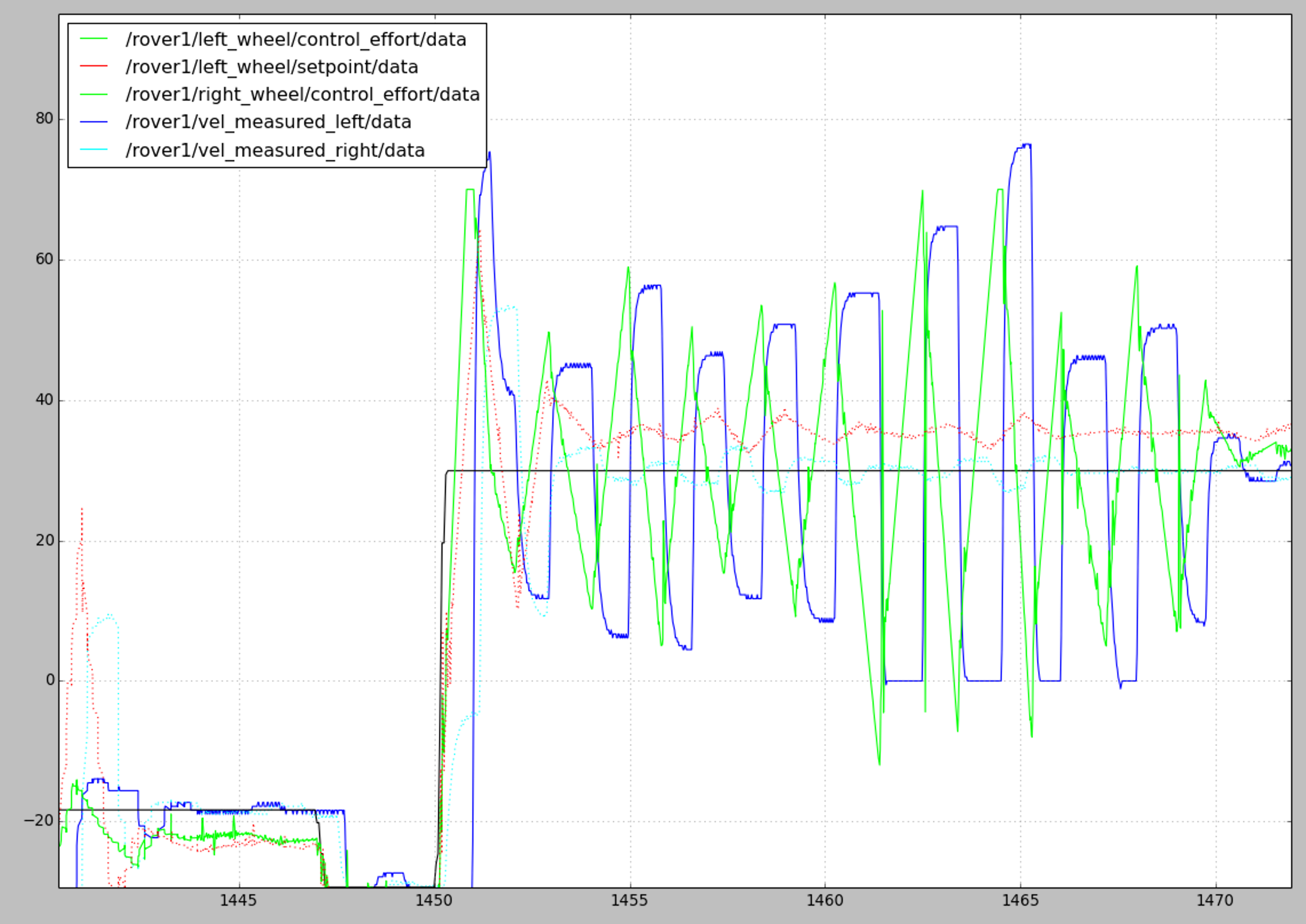 That is actually ...


What is the control_effort produced by the controller? You now focus on the controller, but it could actually be the input to the controller (vel_measured) which is to blame here. looking at the control effort you can hopefully see if the controller or the state starts to deviate first and how the controller responds.
As for windup, that is basically a limit for the integrator part of the PID controller
it's definitely a weird problem. My first guess would be the Raspberry Pi slowing down due to over heating and the control updates becoming further apart. Investigate that. Anything that takes 30 minutes to happen should make you consider temp.
@davekroezen@billy thank you for you suggestions, I updated the question
Maybe check the CPU load with
top(or whatever the RPi equivalent is). Displaying the plots puts a very heavy load on the CPU, maybe that's the cause.To check if the PID package is the cause, you could install the PID package on a regular PC and run the demo for 30 minutes or more. That would make me feel more confident.