ROS Resources: Documentation | Support | Discussion Forum | Index | Service Status | ros @ Robotics Stack Exchange
Ask Your Question
0

Indoor robot navigation with lasers

asked 2019-12-21 03:18:28 -0500

Marcus Barnet gravatar image

updated 2019-12-22 12:13:53 -0500

I have a mobile robot that moves inside an empty room with four walls and it should follow a specific path described as a series of x and y values. I was thinking to mount on the mobile robot four distance laser sensors for natural objects without reflectors (I can't use range lasers because the room is 80x50 meters and the range lasers usually cover up to 20 meters).

Please, see the attached picture and let's say we have a robot (green square) with the four distance lasers mounted along its four cardinal points and it is moving since the room (black square) and it has to follow the blue square path with starting point is x3, y3.

With the laser sensors it can measure its distance from the walls, in each moment, but how can I make it move accordingly with the goal coordinates?

Is there any ROS node which I can use as starting point to develop my ROS node? Do you have suggestions on the algorithm to use or on other sensors/methods?

Does the laser/scan topic work fine with laser distance sensors?

image description

edit retag flag offensive close merge delete

Comments

Hello guys,

We have a precise (±2cm) indoor navigation system (Indoor “GPS”) that is designed to provide real-time location coordinates for autonomous robots, vehicles, AR and VR system.

Demo how it works: https://www.youtube.com/channel/UC4O_kJBQrKC-NCgidS_4N7g/videos.

Basics: You have stationary beacons (not Bluetooth or WiFi) every 10-50 meters. And you trace a mobile beacon on your robot with ±2cm precision. You get the coordinates either directly from the beacon on your robot via USB or UART or SPI or I2C; or you can get data from the central controller - depending on the needs of your system. Detailed description of the protocol is available.

More information is on marvelmind.com I will be happy to provide you with more information, if needed.

P.S.

You can use the following coupon as "Welcome Discount" 3% OFF srg_a55k_3

The most important is that the system is readily available and you ...(more)

Sergey_marvelmind gravatar image Sergey_marvelmind  ( 2020-02-17 07:51:16 -0500 )edit

Honestly speaking they look like all the other UWB products that you can find on the market and they provide only +/-50 cm accuracy in best scenarios. I could be interested but I doubt that they can reach a so accurate precision.

Marcus Barnet gravatar image Marcus Barnet  ( 2020-02-17 08:12:30 -0500 )edit

You can contact me by email (check my profile) in order to better talk about your system

Marcus Barnet gravatar image Marcus Barnet  ( 2020-02-17 08:21:47 -0500 )edit

Hi Marcus, Thank you for interest of our system. I do not see your email in the profile. May I ask you to send me mail to sergey(at)marvelmind.com? I will answer for all your questions. Thank you in advance.

Sergey_marvelmind gravatar image Sergey_marvelmind  ( 2020-02-18 00:09:00 -0500 )edit

@Marcus Barnet: it would be interesting (and beneficial to the community) if you could post a comment here with whatever you learn about @Sergey_marvelmind's product.

gvdhoorn gravatar image gvdhoorn  ( 2020-02-18 02:41:47 -0500 )edit

@gvdhoorn yes, I will share everything for sure! @Sergey_marvelmind: I sent you an email.

By the way, i've found another company that provides a very high accuracy (+/-2cm) with radio beacons, but their system is very expensive (>10.000 USD).

Marcus Barnet gravatar image Marcus Barnet  ( 2020-02-18 02:48:43 -0500 )edit

@gvdhoorn if you what I can share all info what you need + additional discount coupon for community.

We have a lot of demo of our products, video and docs.

Just for example

- https://www.youtube.com/watch?v=YAU-WXz26YY - https://www.youtube.com/watch?v=OXetXiDyAZI - https://www.youtube.com/watch?v=MccIB2pUFaM

Sergey_marvelmind gravatar image Sergey_marvelmind  ( 2020-02-18 07:34:45 -0500 )edit

I'm not necessarily interested in your product(s). I just wanted to make sure your comments are not just marketing for your company, but would result in a contribution to the question @Marcus Barnet posted.

If you would have a proper ROS driver (adhering to the relevant REPs, etc), you could perhaps post in the Projects category on ROS Discourse. Plain advertisements are not wanted there though.

gvdhoorn gravatar image gvdhoorn  ( 2020-02-18 07:38:20 -0500 )edit

1 Answer

Sort by » oldest newest most voted
2

answered 2019-12-21 15:50:37 -0500

billy gravatar image

I think the intent of your question is more general than the specific questions you asked, so I'll try to answer:

Specific questions:

but how can I make it move accordingly with the goal coordinates?

Is there any ROS node which I can use as starting point to develop my ROS node? Do you have suggestions on the algorithm to use or on other sensors/methods?

There are several different packages available within ROS to do motion planning with the Navigation Stack sort of being the "hello world" application for robots equiped with Lidar and wheel encoder.

Does the laser/scan topic work fine with laser distance sensors?

You could make your 4 laser distance sensors output data that could be built into a laser/scan message. But that message with only 4 active data points would be of limited use in a typical robot environment.

Input for what I expect is the intent of the post: Give me advice for how to do this.

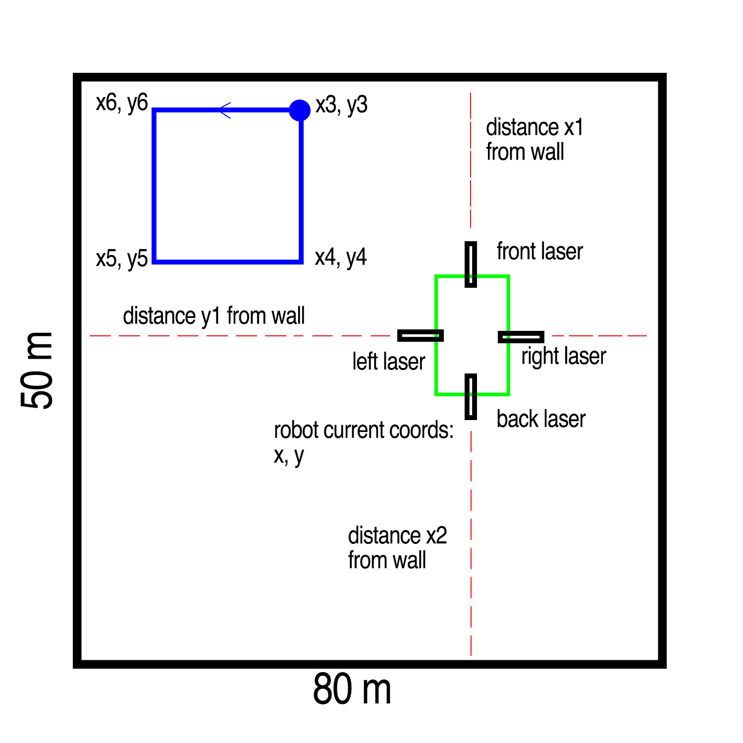
The issue of range for laser scanners is not new. Your proposed idea of 4 distance sensors pointing at the walls will work fine provided you can assure that the robot will

  1. be and stay oriented parallel to the walls
  2. you have some way to either detect obstacles or can be assured there will not be any obstacles.

If 1) and 2) are met you would need to generate an odom message based on the readings of the lasers and move_base could be used to do path planning. Of course there are some caveats regarding noise and accuracy of your lasers. But I'll skip that for now.


In the case for 4 stationary lasers on a platform that cannot be assured to remain oriented, I can imagine an algo that determines accurate long term orientation and location provided the following are met:

  1. you know the starting location and orientation of the robot
  2. you have accurate measurements of the room
  3. the lasers are suitably quiet, stable, and repeatable
  4. you know which way the wheels are rotating (assuming you have wheels)

It's possible AMCL can do this out of the box with 4 points, but not sure. The algo I'm imagining is more deterministic than AMCL (meaning more likely to fail in noisy conditions)

A more general setup that can use well-tested ROS apps would be to mount one or more of your 80m sensors on a rotating platform and generate a multi-angle laser/scan message. With a rotating laser(s) you could see the walls, detect orientation of the robot to the walls and track obstacles.

Many people have put laser ranger finders on rotating platforms and posted youtube videos of the process. I have built a laser scanner based on a cheap range finder. It has better range than the laser scanners I bought but it's noisier.

edit flag offensive delete link more

Comments

Thanks for your support. I forgot to mention that I have a very accurate IMU with heading information on board, the robot moves on mecanum wheels, I know the starting point and the room dimensions are known. Unfortunately the robot should also move in different directions not necessary parallel to the walls. I could mount the range finder on a rotating platform but I don't think it will rotate as fast as a scanner laser do. Moreover, I need to be very accurate because the robot has to reproduce and write (with a paint sprayer) specific shapes on the floor. I can't figure out a good solution to implement this.

Marcus Barnet gravatar image Marcus Barnet  ( 2019-12-21 17:21:12 -0500 )edit
1

Wow. You have a tough challenge. It's a lot bigger than your laser scanner. You will need to develop an algo that not only accurately can move and locate the robot, but that also knows where the wheels are and remembers what it just painted so it can avoid rolling over fresh paint. Of course if you need to paint a closed loop then you may be stuck with one wheel inside the loop.

But back to your laser question: I'd test out the heading indoors if it is based on magnetics. I've not had luck using compass on an indoor robot. Wires, pipes, rebar in concrete can all impact compass performance.In my garage when the robot crosses over an iron sewer pipe buried 1 meter down, the compass deflects by ~15 degrees. IMU will drift over time. You really need a stationary reference like the ...(more)

billy gravatar image billy  ( 2019-12-21 23:48:52 -0500 )edit

Fortunately, I can let the wheels to roll over fresh paint! The imu is a mti-300 AHRS from Xsens which is very accurate but is is based on magnetic, I guess. I can use markers or reflectors but the problem is the long distance (the room is huge). Speed is not mandatory, I prefer accuracy over speed. Unfortunately, long range is necessary since the room is wide, unless we can use some kind of solution based on short range.. but I don't know if such solution exists.

Marcus Barnet gravatar image Marcus Barnet  ( 2019-12-22 05:15:45 -0500 )edit

Just an observation:

You could make your 4 laser distance sensors output data that could be built into a laser/scan message.

don't do this. Distance sensors are very different from laser scanners, or at least in the type of output they produce.

For one thing, laserscan messages essentially encode sensor data in polar coordinates. 4 distance sensors do not. For distance sensors, use sensor_msgs/Range. For multiple sensors (and if desired), use sensor_msgs/PointCloud2, which supports encoding measurements coming from 'arbitrarily' mounted sensors that just happen to result in points in space.

Using LaserScan for something not a laser scan violates semantics.

gvdhoorn gravatar image gvdhoorn  ( 2019-12-22 06:47:24 -0500 )edit
1

@Marcus Barnet: the image you show labels the distances as "distance x1 from wall" implying that x1 is also from a certain wall, but from your later comments it would appear that is not the case. The scanners could be detecting reflections from any of the four walls, correct?

gvdhoorn gravatar image gvdhoorn  ( 2019-12-22 06:49:53 -0500 )edit

Yes each sensor measures distance from each wall, every moment. They detect reflections from wall and I can even use additional markers/detectors if needed. May be using additional markers can lower the maximum long distance required by lasers?

Marcus Barnet gravatar image Marcus Barnet  ( 2019-12-22 07:10:45 -0500 )edit

If I use a scanner laser (like the LMS111 or the UTM-30LX), I place different markers all over the room and I create an accurate 2D map, the robot can move by using AMCL and move_base? because I think it's hard to use a distance laser sensor with AMCL

Marcus Barnet gravatar image Marcus Barnet  ( 2019-12-22 12:13:40 -0500 )edit
1

Yes. A laser scanner and wheel encoders is what is used is the simplest implementation of AMCL and move_base AKA The Navigation Stack. Just out of curiosity, why are you considering adding markers?

billy gravatar image billy  ( 2019-12-23 02:42:23 -0500 )edit

Question Tools

1 follower

Stats

Asked: 2019-12-21 03:18:28 -0500

Seen: 978 times

Last updated: Dec 22 '19