
Gazebo ros control position controller joints problem
Hi,
I am currently working on a project using a vehicle of type EasyMile Ez10 and I have problems when it comes to control both the steering and linear joints. I am currently using Gazebo 7 with ROS Kinetic.
The urdf model in Gazebo has 8 joints and transmissions: 4 continuous (velocity controller) to move the model forward and 4 revolute (position controller) to turn each wheel (like a double Ackermann in which the back wheels mirror the front ones); The description tree of the wheels is like this one:

and this is the model:
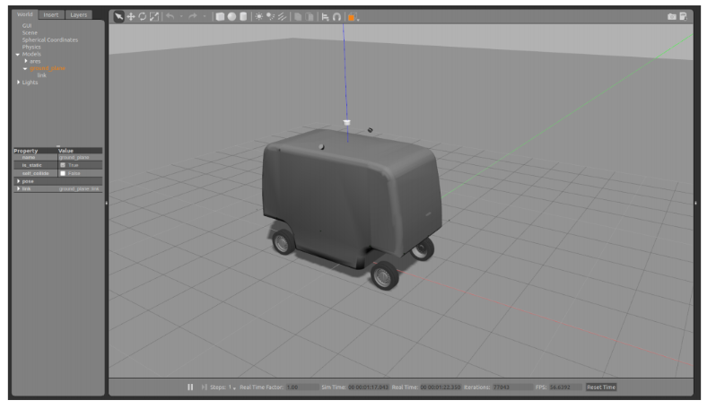
The problem arises when I try to command the joints. If I try to spin the steer joints, the effort applied to each joint by the controller is shared between the parent (axle_joint for steering wheels) and the child (linear joints for movement), hence, the steer joint spin properly but the linear joint moves like if I applied also an effort to it. An example of that behavior can be found here:
https://drive.google.com/open?id=1RVh...
I think is a problem of contacts with the floor and the mass of the model (2000 kg) but I tried to modify the floors properties and ODE parameter with no avail.
Thanks for the help.
Edit: Ok, thanks for the suggestions. I have added new links for resources. Since I do not have enough karma I am not able to post them here direcly.
This is the urdf regarding the wheels of the model:
<robot name="wheel" xmlns:xacro="http://www.ros.org/wiki/xacro">

  <xacro:property name="M_PI" value="3.1415926535897931" />
  <!-- Wheels -->

  <xacro:macro name="cylinder_inertia" params="m r h">
    <inertia  ixx="${m*(3*r*r+h*h)/12}" ixy = "0.0" ixz = "0.0"
              iyy="${m*r*r/2}" iyz = "0.0"
              izz="${m*(3*r*r+h*h)/12}" />
  </xacro:macro>

  <xacro:macro name="rubber_wheel" params="prefix parent wheel_radius wheel_width wheel_mass orientation *origin">

    <!--WHEEL TIRE -->
    <link name="${prefix}_wheel">
      <visual>
        <!-- HIGH RESOLUTION WHEELS -->
        <xacro:if value="${orientation == 0}">
          <origin xyz="0 ${-wheel_width/2} ${-wheel_radius}" rpy="0 0 ${orientation}" />
        </xacro:if>
        <xacro:if value="${orientation == M_PI}">
          <origin xyz="0 ${wheel_width/2} ${-wheel_radius}" rpy="0 0 ${orientation}" />
        </xacro:if>
        <geometry>
            <mesh scale="0.061 0.061 0.061" filename="file:///$(find ares_description)/meshes/wheels/wheel.dae"/>
        </geometry>
      </visual>
      <collision>
        <origin xyz="0 0 0" rpy="${M_PI/2} 0 0" />
        <geometry>
          <cylinder length="${wheel_width}" radius="${wheel_radius}" />
        </geometry>
      </collision>
      <inertial>
        <mass value="${wheel_mass}" />
        <origin xyz="0 0 0" />
        <cylinder_inertia  m="${wheel_mass}" r="${wheel_radius}" h="${wheel_width}" /> <!-- macro defined at the beginning of this document -->
      </inertial>
    </link>

    <!-- Virtual link for two joints -->
    <link name="${prefix}_wheel_axle">
      <inertial>
        <mass value="${wheel_mass}" />
        <origin xyz="0 0 0" />
        <cylinder_inertia  m="${wheel_mass}" r="${wheel_radius}" h="${wheel_width}" /> <!-- macro defined at the beginning of ...
You need to update your sharing settings for the links. We don't have access.
Ideally, screenshots are attached to the question directly and urdf/xacro/code and terminal output are copy-pasted into the text as well.
And if possible: a (short) gif of a video would also be preferred over a google drive link, as those typically disappear.
I've given OP sufficient karma to do that.
I've just fixed your karma. For some reason it got deducted earlier. You should now be able to post the images as well.
One quick comment. You describe the continuous wheel drive joints as linear. Prismatic joints are usually described as linear, so this is a confusing comment. Maybe wheel 'drive' would be clearer.
Ok. The joints marked as "cont." are supposed to be the ones that moves the model (I called it linear control but it can be changed to be more precise).
It's possible the effect you're seeing is caused by friction from the floor. Can you try lifting the robot off the ground so the wheel is in mid air and testing this again.
Yes, actually when the model is in the air the control is just smooth. I tried to change ODE parameter of the floor and the joints but the effect persists.
@Weasfas: off-topic, but is that a wepod?