
Odometry message for ackerman car
Hello , I have an Ackerman car which I want to calculate its velocity using wheel encoders to feed it as odometry message to robot localization. I'm confused what should be the proper calculations for odometry message velocity for an Ackerman car. I assigned the child_frame_id of the message to the base footprint of the car , so the velocity is with respect to the base_footprint of the car (which is in the middle between the rear wheels).
I used 3 models and not sure which is the right one ??
1st model:
(Calculate right rear and left rear wheels velocities and get the steering angle of the car from another sensor)
speed= (vR + vL)/ 2.0
vx = speed * math.cos(wheelAngle)
vy = speed * math.sin(wheelAngle)
odomMsg.twist.twist.linear.x = vx
odomMsg.twist.twist.linear.y = vy
odomMsg.header.frame_id = 'odom'
odomMsg.child_frame_id = 'base_footprint'
2nd model:
(Calculate right rear and left rear wheels velocities and measure the distance between the 2 rear wheels)
LenghtBetweenTwoWheels=1.01
speed= (vR + vL)/ 2.0
v_th=(vR - vL)/ LenghtBetweenTwoWheels
vx = speed
vy = 0.0
odomMsg.twist.twist.linear.x = vx
odomMsg.twist.twist.linear.y = vy
odomMsg.twist.twist.angular.z = v_th
odomMsg.header.frame_id = 'odom'
odomMsg.child_frame_id = 'base_footprint'
3rd model:
(Calculate right rear and left rear wheels velocities and get the steering angle of the car from another sensor)
wheelBase=1.68
speed= (vR + vL)/ 2.0
v_th=speed*tan(wheelAngle)/ wheelBase
vx = speed
vy = 0.0
odomMsg.twist.twist.linear.x = vx
odomMsg.twist.twist.linear.y = vy
odomMsg.twist.twist.angular.z = v_th
odomMsg.header.frame_id = 'odom'
odomMsg.child_frame_id = 'base_footprint'
Any help ? Thank you
EDIT1:
a- My wheel encoders only ticks 52 each turn (The wheel diameter = 0.436m) so The difference between vR & vL wouldn't be very expressive, So I was hoping the third model is correct.
b- I tried the 3 equations: Used 3 sets of robot_localization nodes with same setup :
Setup:
ekf_local_node :
- world_frame: odom
- imu0: /imu
- odom0:/wheel_odom(i)
- output:/odometry/filtered1 "not used"
ekf_global_node :
- world_frame: map
- imu0: /imu
- odom0:/wheel_odom(i)
- output:/odom(i)
The only difference of the 3 set of nodes is that odom0 is /wheel_odom1 or /wheel_odom2 or /wheel_odom3 . Each of these topics calculate twist message according to one equation of last three models .
I turned 360 deg with the car ( used my max wheel angle ) and logged the results of the three ekf_nodes (odom)
The result was as shown in the pic:
yellow line : is the real turn ( using a 1 cm RTK gps with imu orientation)
red line : is the odom output from the first model equation (vx , vy)
green line : is the odom output from the second model equation (vx , vth) (vth=(vR - vL)/ LenghtBetweenTwoWheels)
blue line : is the odom output from the third model equation (vx , vth) (v_th=speed*tan(wheelAngle)/ wheelBase)
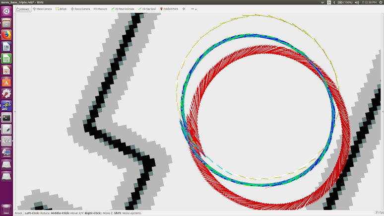
-There is no difference between the second and third model result . Also , I tried to put vth = zero . And the same result happens. -All three equation doesn ...


The image is not showing up for me.
Sorry , I updated the pic
Please post your full EKF config, as well as a sample message from every sensor input.
By the way, if it didn't use theta velocity, you wouldn't see a circle. What makes you think it's ignoring it?
Thank you , I added my full config and sample messages .
Sorry, downloading bags and going through them is going to take more time than I have right now. Can you please paste your full EKF config and sample input messages inside the question itself? Use the code formatting.
what steering sensor were you planning on using?
pot slider ... some thing like that : http://www.surplussales.com/Potentiom...