Hard iron correction of IMU from rosbag

Hello all,
I am using the phidgets_imu package with four Phidgets Spatial 3/3/3 IMU sensors to get pose estimation of both sections of an articulated vehicle. The vehicle has 2 DOF articulation at the center of the vehicle. I.e. the front and rear of the vehicle can yaw and roll independently. The machine is primarily steel which, obviously, messes with the magnetometers. There is one IMU on each corner of the vehicle.
I have them all connected to a central unit using ROS, but can't do so on Windows (transmission distance has been an issue with USB but LAN works fine). I have collected several hours worth of IMU data in bag files so far.
I am using imu_filter_madgwick to the filter the IMUs. I'm aware that hard iron corrections can be added to the filter but I don't know how to compute them. From what I understand, the points should form a sphere and the coordinates of center of that sphere are the correction parameters. I tried finding the average of the max and min for x, y, z axes but that has obvious flaws. How do I fit a sphere to the points? Is that even the correct procedure? Or, has some brilliant person already got a script to do this?
Also, is it possible to set the corrections in the phidgets_imu node itself? I want to implement an EKF anyway so I'd rather not include the madgwick filter as well.
UPDATE 1:
I've collected IMU data over a 7.5 hour period. This is the raw (unfiltered) data from the /imu_data/mag (sensor_msgs/MagneticField) topic. The vehicle trajectory during this period was tracked via GPS. The output is below. For reference, the straight section at the top is about 250m long.
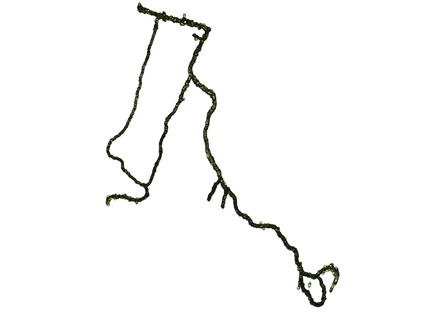
One of the IMUs attached to the machine has the following output over the period.
xy plane
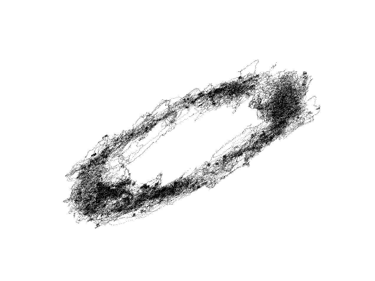
xz plane
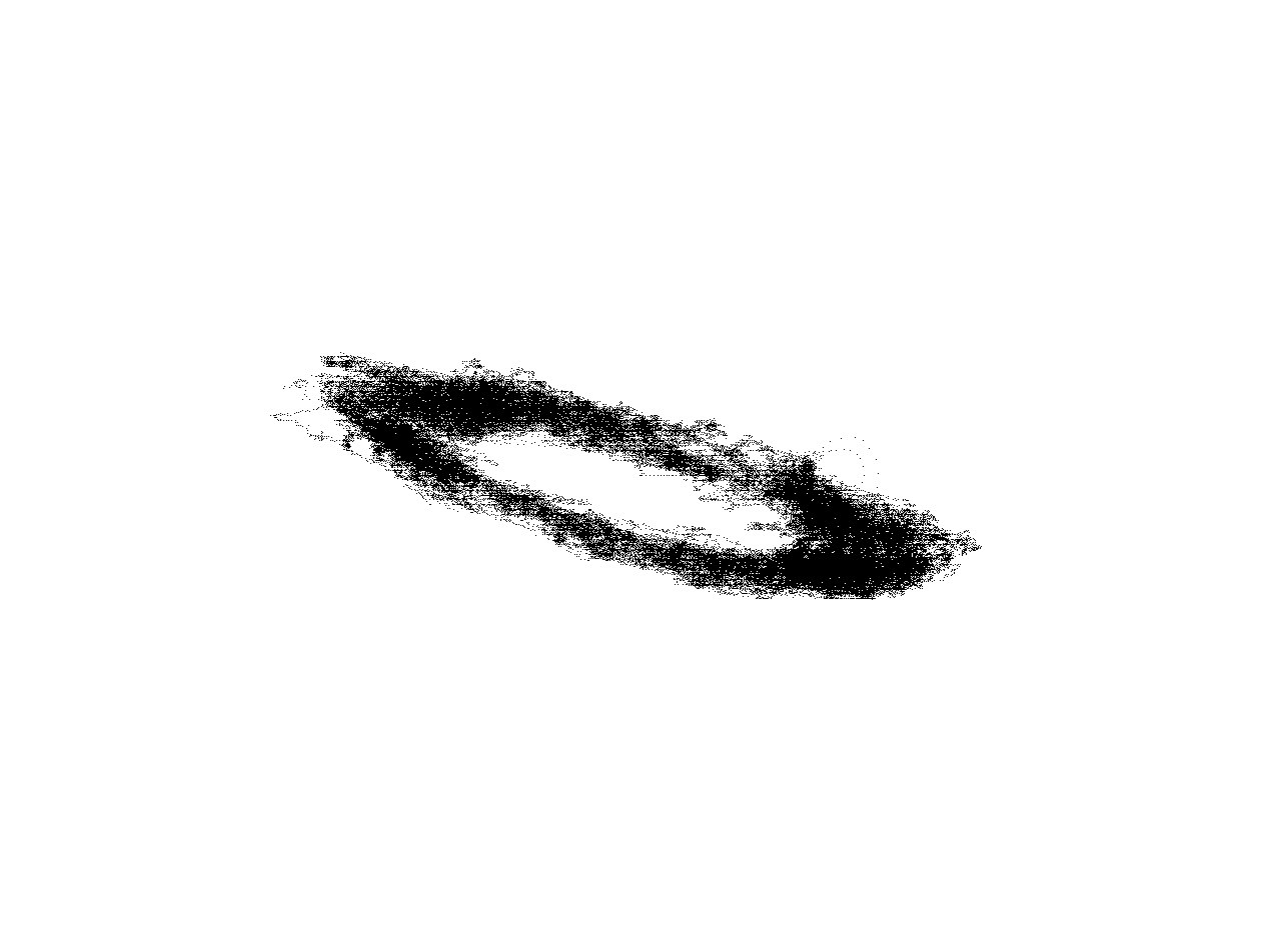
yz plane
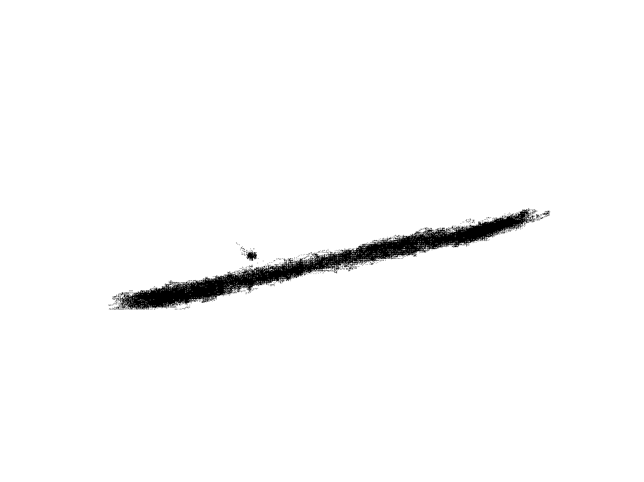
All four IMUs (yup.... four) attached to the vehicle have different outputs, as is to be expected being uncalibrated.
Either way, I expected the points to normalized about some point (which could be used for calibration). And, while these points do seem to lie in a rough ellipse, the variation can't easily be explained by noise (at least to me).
UPDATE 2:
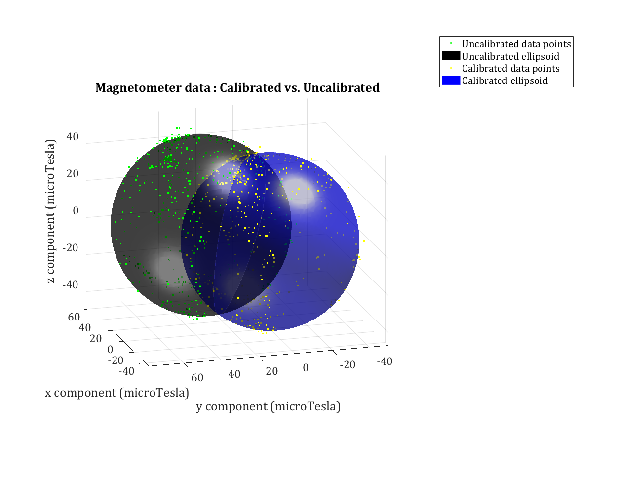
Here is a quick test with a calibrated (not perfectly, but close enough) IMU (same type). Fitting a sphere works very well. The square at the center of the sphere is the origin.
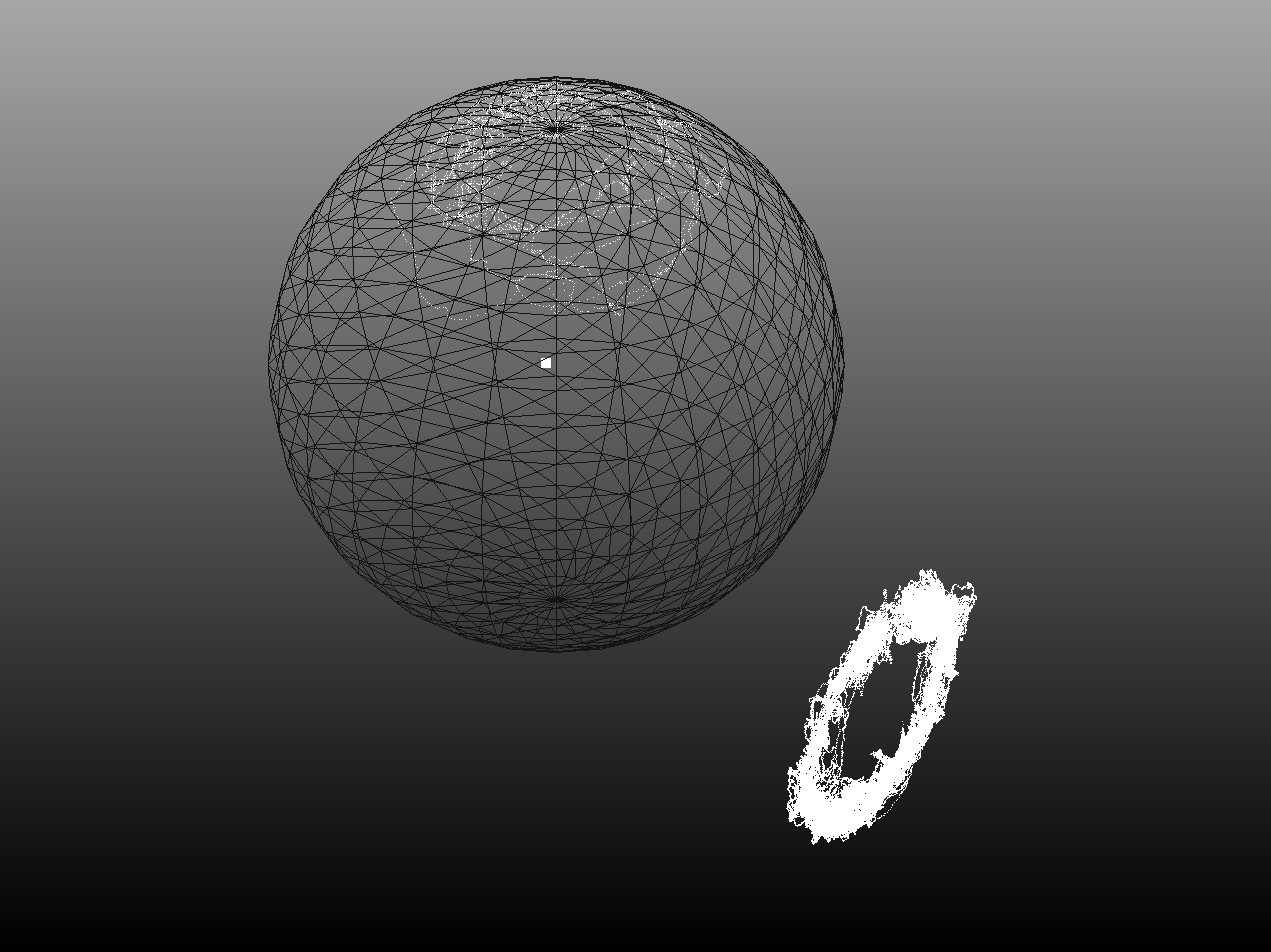
Its not easy to see from a 2D image, but it looks like the IMU on the machines' output is being distorted from the expected sphere into an ellipsoid. So it appears that I have to transform the points into a sphere and then use the center of that sphere to calibrate the IMU. Anyone know how to do that with such a small section of the ellipsoid defined?