
ray sensor not publishing points properly

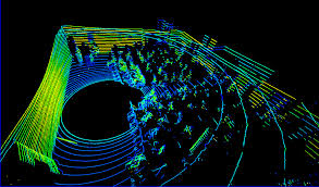
I was trying to visualise velodyne hdl 32 in rviz and the point cloud created by this sensor in rviz, but the output point cloud is not coming realistic, as i've seen it should come like this
but i am visualising the point cloud in rviz like  :
:
First i though that this kind of output is coming because angular velocity of velodyne is less but even after i made it rotate faster, same type of output point cloud comes, so can anyone explain me what is this happening. I am using a ray sensor as laser source for velodyne.
  <gazebo>
    <plugin name="gazebo_ros_control" filename="libgazebo_ros_control.so">
      <robotNamespace>/laser</robotNamespace>
      <robotSimType>gazebo_ros_control/DefaultRobotHWSim</robotSimType>
    </plugin>
  </gazebo>
<gazebo reference="top">
  <sensor type="ray" name="head_hokuyo_sensor">
    <pose>0 0 0.09 1.5708 0 -1.5708</pose>
    <visualize>true</visualize>
    <update_rate>30</update_rate>
    <ray>
     <noise>
      <type>gaussian</type>
      <mean>0.0</mean>
      <stddev>0.1</stddev>
     </noise>
      <scan>
        <horizontal>
          <samples>32</samples>
          <resolution>1</resolution>
          <min_angle>-0.53529248</min_angle>
          <max_angle>0.18622663

</max_angle>
        </horizontal>
      </scan>
      <range>
        <min>0.05</min>
        <max>70</max>
        <resolution>0.02</resolution>
      </range>
    </ray>
    <plugin name="hokuyo_node" filename="libgazebo_ros_laser.so"> <-- or libgazebo_ros_gpu_laser-->
      <topicName>/myrobot1/laser/scan</topicName>
      <frameName>base</frameName>
    </plugin>
  </sensor>

</gazebo>
the ray sensors in gazebo is seen like:
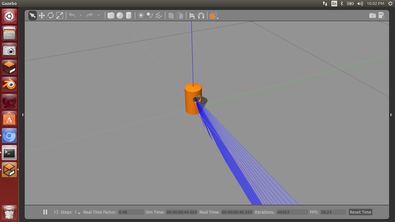 I'm using ros indigo with gazebo 7.4. i also tired gpy_ray sensor and block_laser but they didn't worked.
My velodyne xacro file:
I'm using ros indigo with gazebo 7.4. i also tired gpy_ray sensor and block_laser but they didn't worked.
My velodyne xacro file:
<?xml version="1.0"?>
<robot name="laser" xmlns:xacro="http://ros.org/wiki/xacro">
<xacro:include filename="$(find myrobot1_description)/urdf/laser.gazebo" />
<xacro:include filename="$(find myrobot1_description)/urdf/materials.xacro" />

  <link name="base">

    <visual>
      <origin rpy="0 0 0" xyz="0 0 0.078335"/>
      <geometry>
        <mesh filename="package://myrobot1_description/meshes/velodyne_base.dae"/>
      </geometry>
      <material name="red"/>
    </visual>

    <collision>
      <origin rpy="0 0 0" xyz="0 0 0.078335"/>
      <geometry>
        <mesh filename="package://myrobot1_description/meshes/velodyne_base.dae"/>
      </geometry>
    </collision>

    <inertial>
      <origin rpy="0 0 0" xyz="0 0 0.078335"/>
      <mass value="0.5"/>
      <inertia ixx="0.000090623" ixy="0.0" ixz="0.0" iyy="0.000090623" iyz="0.0" izz="0.000091036"/>
    </inertial>

  </link>

  <link name="top">
    <visual>
      <origin rpy="0 0 0" xyz="0 0 0"/>
      <geometry>
        <mesh filename="package://myrobot1_description/meshes/velodyne_top.dae"/>
      </geometry>
      <material name="white"/>
    </visual>

    <collision>
      <origin rpy="0 0 0" xyz="0 0 0"/>
      <geometry>
        <mesh filename="package://myrobot1_description/meshes/velodyne_top.dae"/>
      </geometry>
    </collision>

    <inertial>
      <mass value="0.5"/>
      <inertia ixx="0.000090623" ixy="0.0" ixz="0.0" iyy="0.000090623" iyz="0.0" izz="0.000091036"/>
    </inertial>
  </link>

  <joint name="joint1" type="revolute">
    <origin rpy="0 0 0" xyz="0 0 0.077"/>
    <axis xyz="0 0 1"/>
    <limit effort="1000.0" lower="-10000000000000000" upper="10000000000000000" velocity="0.5"/>
    <parent link="base"/>
    <child link="top"/>
  </joint>

  <transmission name="tran1">
    <type>transmission_interface/SimpleTransmission</type>
    <joint name="joint1">
      <hardwareInterface>EffortJointInterface</hardwareInterface>
    </joint>
    <actuator name="motor1">
      <hardwareInterface>EffortJointInterface</hardwareInterface>
      <mechanicalReduction>1</mechanicalReduction>
    </actuator>
  </transmission>

</robot>
I also succesfully used block_lase sensor and plugin but still i ...

Are you using the gazebo velodyne plugin?
I have modified that same sdf file of velodyne sensor to xacro format so i can launch it from ros node and than visualize it in rviz and than control its velocity from ros topic. I have added
gazebo_ros_laserplugin below the ray sensor element in urdf.I am still confused. You are using gazebo, and not data from a real device? You are using rviz to see the result?
Yes i am trying to simulate a velodyne hdl_32 laser sensor in gazebo and than by using ray sensor and gazebo_ros_gpu plugin i am subscring the point clouds published by it inside the rviz for visualization how is it working. i also used gpu_ray_plugin but it also shows same output points.