ROS Resources: Documentation | Support | Discussion Forum | Index | Service Status | ros @ Robotics Stack Exchange
Ask Your Question
0

Error while building map in slam_gmapping.

asked 2016-01-21 12:00:16 -0500

Kishore Kumar gravatar image

updated 2016-10-24 09:06:20 -0500

ngrennan gravatar image

I have recorded the rosbag data by simulating the robot in gazebo. when i try to build the map with the command rosrun gmapping slam_gmapping scan:=/rrbot/laser/scan _base_frame:=Base_plate by playing back the logged data i endup with bellow error

 [ WARN] [1453398305.145461344]: Laser has to be mounted planar! Z-coordinate has to be 1 or -1, but gave: -0.03982
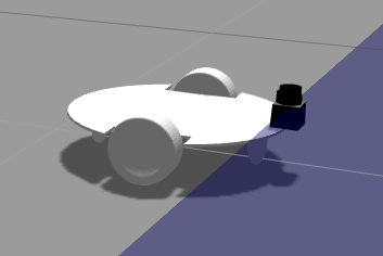
My robot model

image description

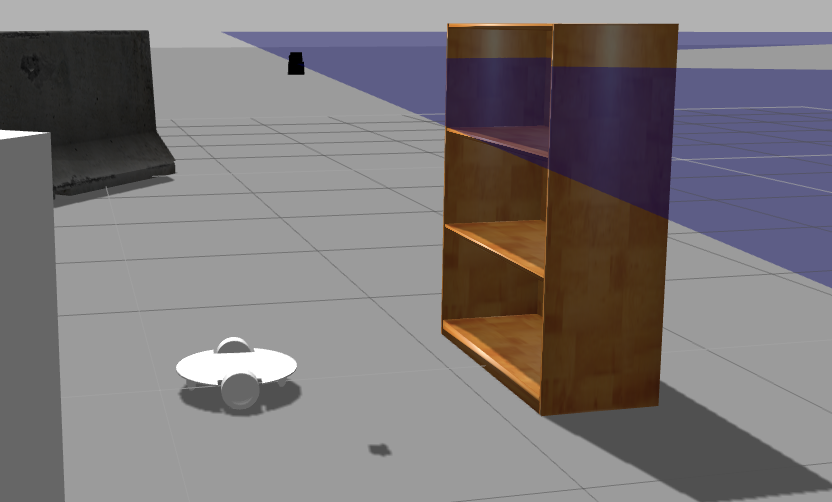
After few iterations, i was able to build the map by modifying joint origin in my URDF file from <origin xyz="0 -0.040 0.2" rpy="-29.85 4.75 0"/> to <origin xyz="0 -1 0.2" rpy="-29.85 4.75 0"/> but my robot model become weird as below.

image description

URDF file

<?xml   version="1.0"?>
<robot
  name="JMbot1.1">
  <link
    name="Base_plate">
    <inertial>
      <origin
        xyz="9.28103095721513E-18 -0.00236910483921667 1.69476737537172E-19"
        rpy="0 0 0" />
      <mass
        value="0.553781193313651" />
      <inertia
        ixx="0.00613802647719325"
        ixy="-5.56633892187664E-20"
        ixz="1.95355359086701E-19"
        iyy="0.0102825986842358"
        iyz="3.22575373206078E-19"
        izz="0.00414996381570526" />
    </inertial>
    <visual>
      <origin
        xyz="0 0 0"
        rpy="0 0 0" />
      <geometry>
        <mesh
          filename="package://jmbot1_description/meshes/Base_plate.STL" />
      </geometry>
      <material
        name="">
        <color
          rgba="0.749019607843137 0.749019607843137 0.749019607843137 1" />
      </material>
    </visual>
    <collision>
      <origin
        xyz="0 0 0"
        rpy="0 0 0" />
      <geometry>
        <mesh
          filename="package://jmbot1_description/meshes/Base_plate.STL" />
      </geometry>
    </collision>
  </link>
  <link
    name="Wheel_R">
    <inertial>
      <origin
        xyz="-0.0394771489417549 -5.20417042793042E-18 1.73472347597681E-18"
        rpy="0 0 0" />
      <mass
        value="0.450643534719172" />
      <inertia
        ixx="0.000916081598048295"
        ixy="1.48930401404157E-20"
        ixz="-9.81573335914851E-21"
        iyy="0.000533948766711724"
        iyz="0"
        izz="0.000533948766711724" />
    </inertial>
    <visual>
      <origin
        xyz="0 0 0"
        rpy="0 0 0" />
      <geometry>
        <mesh
          filename="package://jmbot1_description/meshes/Wheel_R.STL" />
      </geometry>
      <material
        name="">
        <color
          rgba="0.749019607843137 0.749019607843137 0.749019607843137 1" />
      </material>
    </visual>
    <collision>
      <origin
        xyz="0 0 0"
        rpy="0 0 0" />
      <geometry>
        <mesh
          filename="package://jmbot1_description/meshes/Wheel_R.STL" />
      </geometry>
    </collision>
  </link>
  <joint
    name="Wheel_R"
    type="continuous">
    <origin
      xyz="0.135 0.015 0"
      rpy="1.4389236251236 -2.11732407237853E-18 3.14159265358979" />
    <parent
      link="Base_plate" />
    <child
      link="Wheel_R" />
    <axis
      xyz="1 0 0" />
  </joint>
  <link
    name="Wheel_L">
    <inertial>
      <origin
        xyz="-0.0394771489417549 1.21430643318377E-17 8.67361737988404E-18"
        rpy="0 0 0" />
      <mass
        value="0.450643534719172" />
      <inertia
        ixx="0.000916081598048295"
        ixy="2.90916462871053E-20"
        ixz="-2.96782618561828E-20"
        iyy="0.000533948766711724"
        iyz="5.42101086242752E-20"
        izz="0.000533948766711724" />
    </inertial>
    <visual>
      <origin
        xyz="0 0 0"
        rpy="0 0 0" />
      <geometry>
        <mesh
          filename="package://jmbot1_description/meshes/Wheel_L.STL" />
      </geometry>
      <material
        name="">
        <color
          rgba="0.749019607843137 0.749019607843137 0.749019607843137 1" />
      </material>
    </visual>
    <collision>
      <origin
        xyz="0 0 0"
        rpy="0 0 0" />
      <geometry>
        <mesh
          filename="package://jmbot1_description/meshes/Wheel_L.STL" />
      </geometry>
    </collision>
  </link>
  <joint
    name="Wheel_L"
    type="continuous">
    <origin
      xyz="-0.135 0.015 0"
      rpy="0.928716950811488 0 0" />
    <parent
      link="Base_plate" />
    <child
      link="Wheel_L" />
    <axis
      xyz="-1 0 0" />
  </joint>
  <link
    name="Castor_F">
    <inertial>
      <origin
        xyz="-4.16333634234434E-17 0 0.03116425205832"
        rpy="0 0 0" />
      <mass
        value="0.0565552012132997" />
      <inertia
        ixx="2.44755054701354E-05"
        ixy="-6.23799465703127E-37"
        ixz="-1.01877548447475E-20"
        iyy="2.44755054701354E-05"
        iyz="8 ...
(more)
edit retag flag offensive close merge delete

Comments

Well, you have roll and pitch values, even though the scanner seems to be planar.

Are you sure that those values are correct? I'd say that you would need only a yaw value...

Maybe add or link to your urdf for people to help...

mgruhler gravatar image mgruhler  ( 2016-01-22 07:10:22 -0500 )edit

I have added my URDF file for reference. please point out where have i gone wrong.

Kishore Kumar gravatar image Kishore Kumar  ( 2016-01-22 07:49:56 -0500 )edit

2 Answers

Sort by ยป oldest newest most voted
1

answered 2016-02-02 07:49:35 -0500

It looks like your the base link of your robot is not oriented in the standard ROS way (see REP-103). As mentioned there, x should point forward, y left, z up. This most likely is an artifact from the converting the model from SolidWorks to ROS.

I see two ways of fixing this:

  • Edit the URDF model and modify it so the link frames are oriented correctly. For the geometries to be placed correctly, you either have to adjust the origin tags for visual and collision geometries correctly, or you modify the mesh files to have their origin oriented according to ROS conventions.
  • If you don't want to edit the URDF, you can add a static_transform_publisher that introduces a standard conforming base_link frame (you have to find the right transform of course):

    rosrun tf static_transform_publisher x y z y p r base_link Base_plate 100

edit flag offensive delete link more

Comments

When i change "hokuyo_joint" origin value to from <origin xyz="0.0 -0.040 0.2" rpy="1.5708 -1.5708 0"/> to <origin xyz="0.0 -1 0.2" rpy="1.5708 -1.5708 0"/> the slam_gmapping node is working fine. Do you still think my base_link orientation is wrong?

Kishore Kumar gravatar image Kishore Kumar  ( 2016-02-02 09:22:24 -0500 )edit

Well let''s say "non-standarf" instead of "wrong", but yes :) Given there is a non-zero rotation between base_link and hokuyo, the base_link appears to be oriented different from the standard convention. If things work for you, that' s ok for the moment, but controllers etc. might have problems.

Stefan Kohlbrecher gravatar image Stefan Kohlbrecher  ( 2016-02-02 11:40:45 -0500 )edit

Is it okay if i change the coordinate system in solidworks and export it again using solidworks2urdf plug-in, because i find its difficult to fix this in ROS, Or can you please help me with this in ROS?

Kishore Kumar gravatar image Kishore Kumar  ( 2016-02-02 12:14:10 -0500 )edit

Please take a look at this image and let me know how to shift the coordinate.

Kishore Kumar gravatar image Kishore Kumar  ( 2016-02-02 12:14:47 -0500 )edit

The correct orientation is linked in REP103 (linked above). As stated there, x has to point forward, y left and z up. Should be ok if you adjust things in SolidWorks.

Stefan Kohlbrecher gravatar image Stefan Kohlbrecher  ( 2016-02-02 13:13:23 -0500 )edit

Thank you, i resolved the issue by re-exporting from solidworks.

Kishore Kumar gravatar image Kishore Kumar  ( 2016-02-03 13:33:41 -0500 )edit
0

answered 2016-01-22 08:19:40 -0500

mgruhler gravatar image

updated 2016-01-22 08:24:07 -0500

The failing check in gmapping is here.

You have set your laser to have pitch roll angles, possibly violating this check. As it seems that your scanner is mounted planar, why do you not only use a yaw value? yaw is rotation around the z-Axis, which should be fine for your case.

So this

<joint name="hokuyo_joint" type="fixed">
    <axis xyz="0 1 0" />                                     <-- not used in fixed joints!
    <origin xyz="0.0 -0.040 0.2" rpy="1.5708 -1.5708 0"/>
    <parent link="Base_plate"/>
    <child link="hokuyo_link"/>
</joint>

should be something like this

<joint name="hokuyo_joint" type="fixed">
    <origin xyz="0.0 -0.040 0.2" rpy="0.0 0.0 3.14159"/>
    <parent link="Base_plate"/>
    <child link="hokuyo_link"/>
</joint>
edit flag offensive delete link more

Comments

The issue persists even after the change. Same error, indicating the value "-0.040" in the origin.

Kishore Kumar gravatar image Kishore Kumar  ( 2016-01-22 09:08:34 -0500 )edit

Could you try setting the rotation to 0, 0, 0 and see if this works? Also, please provide OS, ROS Distro and version of slam_gmapping. This seems to be something very specific...

mgruhler gravatar image mgruhler  ( 2016-01-28 01:18:10 -0500 )edit

when i change the rotation to the given values the orientation of robot changes like this, My OS - Ubuntu 14.04, ROS indigo, slam_gmapping - Version: 1.3.8-0trusty-20151111-0758-+0000

Kishore Kumar gravatar image Kishore Kumar  ( 2016-01-28 12:44:36 -0500 )edit

Question Tools

1 follower

Stats

Asked: 2016-01-21 12:00:16 -0500

Seen: 1,187 times

Last updated: Feb 02 '16