ROS Resources: Documentation | Support | Discussion Forum | Index | Service Status | ros @ Robotics Stack Exchange
Ask Your Question
0

Tf origin is away from the base_link

asked 2016-01-08 11:09:55 -0500

Kishore Kumar gravatar image

updated 2016-01-12 02:00:30 -0500

I have built my differential drive mobile robot in solidworks and converted that to URDF file using soliworks2urdf convertor. I successfully launched and robot and simulated with tele-operation node. Since i am intended to use navigation stack in i viewed the transform of the robot in rviz which resulted as below.

image description

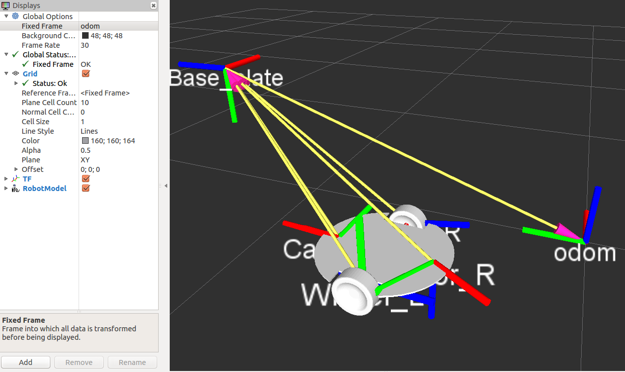
As you can see the base plate is the one which supports the wheels and castors but the tf of base plate is shown away from the actual link and even odom is away from the model. Where have i gone wrong and how to fix this. Refer the URDF of model below.

<?xml   version="1.0"?>
<robot
  name="JMbot">
  <link
    name="Base_plate">
    <inertial>
      <origin
        xyz="-0.3317 0.71959 -0.39019"
        rpy="0 0 0" />
      <mass
        value="0.55378" />
      <inertia
        ixx="0.0061249"
        ixy="0.00016086"
        ixz="-8.6651E-18"
        iyy="0.0041631"
        iyz="-1.4656E-17"
        izz="0.010283" />
    </inertial>
    <visual>
      <origin
        xyz="0 0 0"
        rpy="0 0 0" />
      <geometry>
        <mesh
          filename="package://jmbot_description/meshes/Base_plate.STL" />
      </geometry>
      <material
        name="">
        <color
          rgba="0.74902 0.74902 0.74902 1" />
      </material>
    </visual>
    <collision>
      <origin
        xyz="0 0 0"
        rpy="0 0 0" />
      <geometry>
        <mesh
          filename="package://jmbot_description/meshes/Base_plate.STL" />
      </geometry>
    </collision>
  </link>
  <link
    name="Wheel_R">
    <inertial>
      <origin
        xyz="0.010951 1.1102E-16 -1.1102E-16"
        rpy="0 0 0" />
      <mass
        value="0.45064" />
      <inertia
        ixx="0.00091608"
        ixy="-1.2355E-19"
        ixz="1.0715E-18"
        iyy="0.00053395"
        iyz="-6.7763E-20"
        izz="0.00053395" />
    </inertial>
    <visual>
      <origin
        xyz="0 0 0"
        rpy="0 0 0" />
      <geometry>
        <mesh
          filename="package://jmbot_description/meshes/Wheel_R.STL" />
      </geometry>
      <material
        name="">
        <color
          rgba="0.74902 0.74902 0.74902 1" />
      </material>
    </visual>
    <collision>
      <origin
        xyz="0 0 0"
        rpy="0 0 0" />
      <geometry>
        <mesh
          filename="package://jmbot_description/meshes/Wheel_R.STL" />
      </geometry>
    </collision>
  </link>
  <joint
    name="Wheel_R"
    type="continuous">
    <origin
      xyz="-0.14688 0.40756 -0.73464"
      rpy="-2.7127 -0.081268 -3.1416" />
    <parent
      link="Base_plate" />
    <child
      link="Wheel_R" />
    <axis
      xyz="1 0 0" />
  </joint>
  <link
    name="Wheel_L">
    <inertial>
      <origin
        xyz="-0.039049 2.2204E-16 2.498E-15"
        rpy="0 0 0" />
      <mass
        value="0.45064" />
      <inertia
        ixx="0.00091608"
        ixy="-9.6693E-19"
        ixz="-1.7816E-18"
        iyy="0.00053395"
        iyz="1.3553E-19"
        izz="0.00053395" />
    </inertial>
    <visual>
      <origin
        xyz="0 0 0"
        rpy="0 0 0" />
      <geometry>
        <mesh
          filename="package://jmbot_description/meshes/Wheel_L.STL" />
      </geometry>
      <material
        name="">
        <color
          rgba="0.74902 0.74902 0.74902 1" />
      </material>
    </visual>
    <collision>
      <origin
        xyz="0 0 0"
        rpy="0 0 0" />
      <geometry>
        <mesh
          filename="package://jmbot_description/meshes/Wheel_L.STL" />
      </geometry>
    </collision>
  </link>
  <joint
    name="Wheel_L"
    type="continuous">
    <origin
      xyz="-0.46668 0.40756 -0.70859"
      rpy="2.512 0.081268 3.4272E-15" />
    <parent
      link="Base_plate" />
    <child
      link="Wheel_L" />
    <axis
      xyz="-1 0 0" />
  </joint>
  <link
    name="Castor_F">
    <inertial>
      <origin
        xyz="2.2204E-16 0 0.031164"
        rpy="0 0 0" />
      <mass
        value="0.056555" />
      <inertia
        ixx="2.4476E-05"
        ixy="-2.8588E-35"
        ixz="1.0281E-20"
        iyy="2.4476E-05"
        iyz="-1.2617E-20"
        izz="7.4341E-06" />
    </inertial>
    <visual>
      <origin
        xyz="0 0 0"
        rpy ...
(more)
edit retag flag offensive close merge delete

1 Answer

Sort by ยป oldest newest most voted
0

answered 2016-01-12 04:14:42 -0500

dfornas gravatar image

I think your problem is that the robot is not placed in the center of coordinates in SolidWorks. As a result the first model (the base plate) is displaced this respect to the base frame and all the subsequent joints are also set with respect to this SolidWorks origin. You should try to put the robot in the solidworks origin and then export it again.

edit flag offensive delete link more

Comments

Is there anyway to fix this by editing URDF file?. Because its tedious procedure to start over again

Kishore Kumar gravatar image Kishore Kumar  ( 2016-01-12 06:55:11 -0500 )edit

I think it won't be easy. Moreover your inertial values will probably be wrong also If you change things manually. I usually design the pieces separatelly and build the URDF file manually. It is not very difficult and allows more control, but it is not suited for bigger robots.

dfornas gravatar image dfornas  ( 2016-01-12 07:07:38 -0500 )edit

Nevertheless, if you don't care inertial values you can offset the base_plate visual to be where the base_plate is and then offset the rest of the links to move beside the base plate. Once you figure the offset this should be fairly easy.

dfornas gravatar image dfornas  ( 2016-01-12 07:09:27 -0500 )edit

I reviewed my model in solidworks and the origins seems to be fine can you pls check the pics here

Kishore Kumar gravatar image Kishore Kumar  ( 2016-01-12 08:45:35 -0500 )edit

Well but in the 3rd picture you clearly see the problem: Origin_base_plate should be on top of Origin_global but instead has the same offset. Try to move the origin of the robot in SolidWorks and see If this relationship changes.

dfornas gravatar image dfornas  ( 2016-01-13 02:21:23 -0500 )edit

I would try out the Phobos plugin for Blender: https://github.com/rock-simulation/ph... You could export meshes from SolidWorks as dae, import them into Blender, set up the robot, and export to URDF. Go to https://www.blender.org/download/ and download v. 2.76b for dae import support

robustify gravatar image robustify  ( 2016-03-04 17:52:28 -0500 )edit

Question Tools

1 follower

Stats

Asked: 2016-01-08 11:09:55 -0500

Seen: 1,344 times

Last updated: Jan 12 '16