ROS Resources: Documentation | Support | Discussion Forum | Index | Service Status | ros @ Robotics Stack Exchange
Ask Your Question
0

Question concerning the movement of a 6DOF + frames

asked 2014-08-27 12:05:54 -0500

Andromeda gravatar image

updated 2014-08-27 15:55:43 -0500

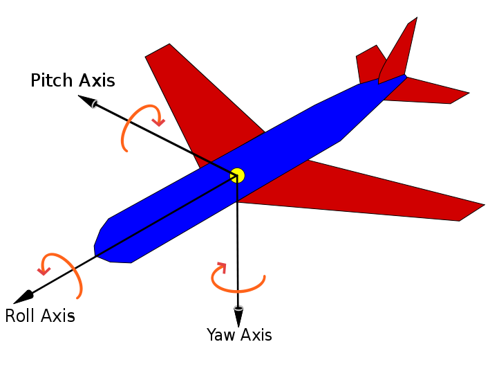
Right now I m writing a small urdf file to simulate the behaviour of a small RC helicopter (or UAV) in Rviz. The flying robot is going to read datas from an IMU and should move in Rviz accordingly to the received angles like in the following picture:

image description

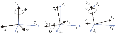
Now...I found a problem writing my code because as stated here is the definition of a "floating" joint deprecated and no more usable. My idea was to define a frame fixed with the robot and a "floating" frame which rotate about all 3 axis (see euler angles as a visual description of my idea):

image description

How can I solve this problem? Defining 3 different frames doesn 't help since the rotation order is very important as you can see during a transformation about one axis then the other and the last one:

image description

I this case I get different orientations depending on the sequence of the rotations. Shortly: 3 frames with a common center is definitely not the way to go...

EDIT: (Thanks foote): another idea could be to think the flying robot as a flying "point". It moves on a reference map. But in this case I face a big problem regarding that from this point of view is not possibile to give the flying point an orientation about one axis (let say yaw), just the absolute localization of the object in the space. Or how about roll? I can describe the movement in reference of a static object in Rviz but not the different position around one axis.

So I would be really happy if you could me some hints and example to realize a small flying object. Perhaps it is only a different way to think or a different perspective of the problem. Anyway any help is much appreciated! :)

Thanks and regards

edit retag flag offensive close merge delete

2 Answers

Sort by ยป oldest newest most voted
1

answered 2014-08-27 15:33:39 -0500

tfoote gravatar image

updated 2014-08-27 16:14:01 -0500

The expected solution for a urdf of a flying robot is that the urdf will contain the robot, and the connection to the world will be done through a localization node which publishes the position of the robot in free space. Usually in relationship to a map, and the URDF does not encompass the total movements of the robot.

Update: The position of the robot in free space is usually captured by the tf coordinate frame. And it can represent a full freespace position and orientation.

edit flag offensive delete link more

Comments

Many thanks for your answer. To be honest it is not clear to me what do you mean with "localization node". Could you please tell me a link or something like that to point me in the right direction? I already tried to search but didn t find anything useful. Regards

Andromeda gravatar image Andromeda  ( 2014-08-28 15:39:48 -0500 )edit

Another question: I was thinking again and maybe I m wrong, but from your explanation seems to me that I can set up in my URDF just one frame (to define the base body of my copter or just to load a .stl file) and then I use only tf to drive the flying robot. Am I right? Thanks in advance

Andromeda gravatar image Andromeda  ( 2014-08-28 15:50:31 -0500 )edit
1

answered 2014-08-27 16:57:02 -0500

Murilo F. M. gravatar image

updated 2014-09-02 16:59:06 -0500

Adding to what @tfoote said, my workaround to the fact that floating joints are not available anymore was to broadcast a base_stabilisedframe, which coincides with my quadrotor's base_link, but rotates along the X- and Y-axis according to the IMU's quaternion (transformed to base_link if an existing imu_link does not coincide with base_linkas well).

After implementing it myself, I found out there is a package called hector_imu_attitude_to_tf, which does exactly that.

This way, when I set the fixed frame in RViz to base_stabilised, I can see the quadrotor roll'ing and pitch'ing. Extending that to broadcast rotation along the Z-axis should be straightforward.

EDIT: Below is an example of how I used the hector_imu_attitude_to_tf package:

<node pkg="hector_imu_attitude_to_tf" type="imu_attitude_to_tf_node" name="base_stabilised_node">
    <param name="base_stabilized_frame" type="string" value="base_stabilised" />
    <param name="base_frame" type="string" value="base_link" />
    <remap from="imu_topic" to="/imu" />
</node>
edit flag offensive delete link more

Comments

Hi Murilo. I really want to implement such a workaround but to be honest I didn t understand the implemented code in the link that you posted. I need just to figure out how this should work. AM I right if I create a frame for the robot, one frame for the IMU and start tracking the transformation...

Andromeda gravatar image Andromeda  ( 2014-08-28 15:42:13 -0500 )edit

...between both? The resulting frame should be the base_stabilised, right? I think I understood the principles, but the implementation is to me not clear. Regards

Andromeda gravatar image Andromeda  ( 2014-08-28 15:43:19 -0500 )edit

I edited my answer and added an example of how I use the package. You just need to add that to your launch file.

Murilo F. M. gravatar image Murilo F. M.  ( 2014-09-02 17:00:07 -0500 )edit

Question Tools

1 follower

Stats

Asked: 2014-08-27 12:05:54 -0500

Seen: 755 times

Last updated: Sep 02 '14