ROS Resources: Documentation | Support | Discussion Forum | Index | Service Status | ros @ Robotics Stack Exchange
Ask Your Question
3

Using Moveit! to Control the End of a Hydraulic Arm in Cartesian Coordinates

asked 2014-08-21 06:14:11 -0500

bjem85 gravatar image

updated 2014-09-04 03:23:34 -0500

I have a small hydraulic arm (similar to an excavator arm) that consists of a rotating base, a boom link and a stick link. The boom and stick links move in a vertical plane whose orientation is defined by the rotating base. I would like to control the distal end (end furtherest from the base) of the stick link in two ways: Cylindrical coordinates and Cartesian Coordinates.

What are the main steps required to achieve this? So far I have a primitive model of my robot arm and have run through the MoveIt setup guide, but I am having difficulty with working out how to implement the joint combinations and kinematic chains. So far the behaviour of MoveIt! seems to be focused in joints only. I could set up an end effector in MoveIt! but the arm does not have an end effector as such.

Here is a screenshot of the situation.

MoveIt! RViz Interface

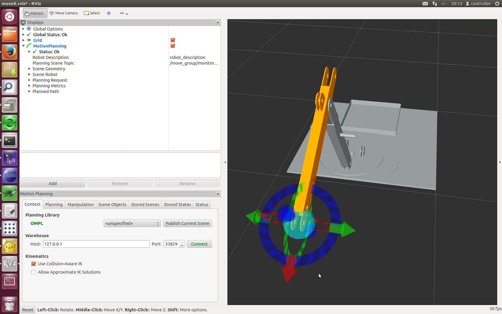
What I have done is that I have defined the tip of the 'stick' (where the ball is) as a universal joint consisting of two continuous joints, with a dummy link in the middle.

I can move the arm fine by dragging the red and blue arrows. However, if I try to move the arm by moving the green arrows it will not move. Such movement should be accommodated by having the base rotate, something that is not happening. Indeed, if I drag the green arrows it 'breaks' the position so that I have to reset it before I can choose any other valid position. Note that if I select a 'random valid' joint end state it does pick states with the base rotated.

I am finding the whole thing perplexing. Can anyone shed light on how I could drag the position of the end of the arm using all three arrows without it breaking anything?

Thanks, Bart

edit retag flag offensive close merge delete

Comments

Forgive my ignorance (as in: I might not fully understand this), but wouldn't defining a kinematic chain work here? Create one including all links, so the "rotating base, boom link and stick link". As long as proper joints have been defined between those links, the planners should be able to work it. Don't try to add joints to groups, then links to the chain simultaneously. Define only one. The end effector isn't needed yet.

gvdhoorn gravatar image gvdhoorn  ( 2014-08-21 06:17:46 -0500 )edit

It does work, in the sense that a solution can be found, but I cannot control the joint angles and coordinates in the way I want to, and I don't see where the MoveIt! setup assistant has any flexibility to let me adjust it to what I want.

bjem85 gravatar image bjem85  ( 2014-08-23 06:36:48 -0500 )edit

You're going to have to be a bit more specific than "what you want". Whay did you try, what didn't work and what do you want to achieve? Please update your question with that information (instead of in the comments). Also, see if the ROS-I tutorial on moveit cfgs can fill in any of the missing pieces.

gvdhoorn gravatar image gvdhoorn  ( 2014-08-23 07:02:43 -0500 )edit

1 Answer

Sort by » oldest newest most voted
1

answered 2014-08-21 08:38:07 -0500

Airuno2L gravatar image

I haven't used Moveit! much, and this might not be what is causing your specific problem, but KDL, which is what Moveit! uses for inverse kinematics by default, is really only meant for arms with at least 6 degrees of freedom.

For arms with less than 6 dof, I would recommend either using an IKFast solution or solving the inverse kinematics by hand. Your arm sounds like an articulated manipulator, so you could google for "inverse kinematics articulated manipulator" and you will likely find a solution that is ready to use (but solving it by hand isn't too hard). Personally, if it were me, I'd just use IKFast because it is straight forward and requires less thinking lol.

As for solving using Cylinderical and Cartesian Coordinates, just solve using Cartesian Coordinates, then have a wrapper functions that converts cylinderical into cartesian before being input to the inverse kinematics solvers...and then convert the output of the IK solver from cartesian back to cylinderical before returning.

edit flag offensive delete link more

Comments

I am trying to follow the standard IKFast instructions, however they skip steps particularly when describing the planning groups and I can't find the worked example they use on the page. I end up with it failing to find a variable to solve.

bjem85 gravatar image bjem85  ( 2014-08-23 06:59:32 -0500 )edit

P.S. I am using the translation3d solver. The physical arm is capable of doing this kind of 3D translation.

bjem85 gravatar image bjem85  ( 2014-08-23 07:01:12 -0500 )edit
1

particularly when describing the planning groups

You shouldn't have to define any planning groups. IKFast plugins are generated using the URDF (converted to collada), and a specification of a chain (you use the openrave-robot.py <myrobot_name>.dae --info links for that). The plugin you generate is then (only) usable for a planning group (chain) that contains the same links and you'll have to figure out the proper type of IK for your manipulator.

gvdhoorn gravatar image gvdhoorn  ( 2014-08-23 07:06:36 -0500 )edit

See ( http://answers.ros.org/question/19188... ) for my experience with IKFast and MoveIt.

bjem85 gravatar image bjem85  ( 2014-09-04 03:29:49 -0500 )edit

You are on the right track! Your problem is indeed caused by a missing 3D IK solver. When you drag the green arrow to the right, you are requesting a 6D pose that is unreachable, since you're not simulateously rotating it. The 3D IK finds the missing rotation for any given 3D translation.

Martin Günther gravatar image Martin Günther  ( 2014-09-04 03:47:32 -0500 )edit

Question Tools

1 follower

Stats

Asked: 2014-08-21 06:14:11 -0500

Seen: 1,994 times

Last updated: Sep 04 '14