Willow Garage has a nice SolidWorks Plugin for exporting URDF. Here is a link and check out everything in there:
http://www.willowgarage.com/blog/2012...
EDIT I have actually tried doing something like this myself. What we are trying to do is called a closed loop joint. From reading around, URDF format does not support closed loop joints because the people who update it "see no need in implementing this functionality". From the using URDF in gazebo 1.9 tutorial: "URDF can not specify the pose of the robot itself within a world. It is also not a universal description format since it cannot specify joint loops (parallel linkages), and it lacks friction and other properties. Additionally, it cannot specify things that are not robots, such as lights, heightmaps, etc."
But on the positive side of things, SDF format seems like it supports closed loop joints. gazebo parallel mechanisms. Even though this post is taking about parallel mechanisms, it is essentially the same thing with trying to connect a child joint, back to its originating parent. More specifically to your scenario, inside of that gazebo parallel mechanisms link is another link to pr2's gripper. It is in sdf format already. In case you did not want to deal with sdf and stick with urdf, it is really easy to convert the urdf to sdf since gazebo already does it every time you load the model. (go to directory of your URDF) gzsdf print (yoururdf.URDF) > (yoursdfname).sdf is all you need.
And from my understanding, I believe you would want your joints set as revolute (in sdf) and just calculate the upper and lower limits (in radians) of how far up and down the actuator angles can go.
Let me know if you make any progress because I am also trying to get the closed loop joints to work. This is all I pretty much knew about it from the research I have done. Hope this gives you a head start.
EDIT 2:
So I have actually been able to successfully define a (little bit more complicated than yours) closed loop joint linkage. The approach that I took may/may not be the most optimal way, but it definitely works since my model won't fall apart in gazebo now..
For your scenario, (assuming you are using the sw_urdf_exporter like i recommended):
- make the base of your robot mechanism the part that is in the most bottom right corner of your picture (so basically the 'non-moving' part), and call it base_link
- Next create a child off of the base_link you just created, for part A in your picture, and call it lets say "mech_top_link" and then call the joint name "mech_top_base_joint" (With joints, try to make them as specific to what two linkages they are jointing). Make sure you set the axis rotation type to revolute as well.
- Once mech_top_link is created, you can then add the ending to that arm (which is at the top right of ...
(more)
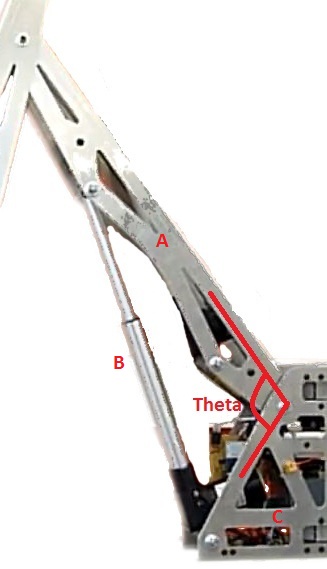


NB: Updated image with member labels. To clarify the question, ow should I use the SW2URDF tool to describe this joint? What i am not sure about is that A and B have the same parent (C) but is A is also a child of B?