
The site is read-only. Please transition to use Robotics Stack Exchange
| ROS Resources: Documentation | Support | Discussion Forum | Index | Service Status | ros @ Robotics Stack Exchange |
| | 1 | initial version |
Doc: sensor_msgs..LaserScan has explanation for all the variables.
Header header            # timestamp in the header is the acquisition time of
                         # the first ray in the scan.
                         #
                         # in frame frame_id, angles are measured around
                         # the positive Z axis (counterclockwise, if Z is up)
                         # with zero angle being forward along the x axis

float32 angle_min        # start angle of the scan [rad]
float32 angle_max        # end angle of the scan [rad]
float32 angle_increment  # angular distance between measurements [rad]

float32 time_increment   # time between measurements [seconds] - if your scanner
                         # is moving, this will be used in interpolating position
                         # of 3d points
float32 scan_time        # time between scans [seconds]

float32 range_min        # minimum range value [m]
float32 range_max        # maximum range value [m]

float32[] ranges         # range data [m] (Note: values < range_min or > range_max should be discarded)
float32[] intensities    # intensity data [device-specific units].  If your
                         # device does not provide intensities, please leave
                         # the array empty.
Obstacle distance calculation is easy
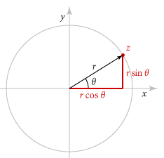
if r, theta are range and angle from laser scan obstacle is at (x,y) = rcos(theta), rsin(theta)
| | 2 | No.2 Revision |
Doc: sensor_msgs..LaserScan has explanation for all the variables.
Header header            # timestamp in the header is the acquisition time of
                         # the first ray in the scan.
                         #
                         # in frame frame_id, angles are measured around
                         # the positive Z axis (counterclockwise, if Z is up)
                         # with zero angle being forward along the x axis

float32 angle_min        # start angle of the scan [rad]
float32 angle_max        # end angle of the scan [rad]
float32 angle_increment  # angular distance between measurements [rad]

float32 time_increment   # time between measurements [seconds] - if your scanner
                         # is moving, this will be used in interpolating position
                         # of 3d points
float32 scan_time        # time between scans [seconds]

float32 range_min        # minimum range value [m]
float32 range_max        # maximum range value [m]

float32[] ranges         # range data [m] (Note: values < range_min or > range_max should be discarded)
float32[] intensities    # intensity data [device-specific units].  If your
                         # device does not provide intensities, please leave
                         # the array empty.
Obstacle distance calculation is easy
if r, theta θ are range and angle from one scan laser scan obstacle is at (x,y) = rcos(theta), rsin(theta)( rcosθ, rsinθ ) in laser frame.
To make sense about θ , here imagine your laser has 180 deg view in looking towards x-axis and ray along postive y-axis is +90 degress and negative y-axis is -90 degree.
agnle_min = -90
agnle_max = 90
| | 3 | No.3 Revision |
Doc: sensor_msgs..LaserScan has explanation for all the variables.
Header header            # timestamp in the header is the acquisition time of
                         # the first ray in the scan.
                         #
                         # in frame frame_id, angles are measured around
                         # the positive Z axis (counterclockwise, if Z is up)
                         # with zero angle being forward along the x axis

float32 angle_min        # start angle of the scan [rad]
float32 angle_max        # end angle of the scan [rad]
float32 angle_increment  # angular distance between measurements [rad]

float32 time_increment   # time between measurements [seconds] - if your scanner
                         # is moving, this will be used in interpolating position
                         # of 3d points
float32 scan_time        # time between scans [seconds]

float32 range_min        # minimum range value [m]
float32 range_max        # maximum range value [m]

float32[] ranges         # range data [m] (Note: values < range_min or > range_max should be discarded)
float32[] intensities    # intensity data [device-specific units].  If your
                         # device does not provide intensities, please leave
                         # the array empty.
Obstacle distance calculation is easy
if r, θ are range and angle from one scan laser scan obstacle is at (x,y) = ( rcosθ, rsinθ ) in laser frame.
To make sense about θ , here imagine your laser has 180 deg view in and now looking towards x-axis and ray along postive y-axis is +90 degress and negative y-axis is -90 degree.
agnle_min = -90
agnle_max = 90
| | 4 | No.4 Revision |
Doc: sensor_msgs..LaserScan has explanation for all the variables.
Looking at the code Publish_a_LaserScan_Message will gives good picture of variables.
laser scanner view of hokuyo URG-04LX-UG01 laser scanner
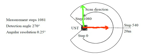
red,green are x,y-axes
Values for above scanner
    angle_min= -135 * (pi/3.14); //angle correspond to FIRST beam in scan ( in rad)
    angle_max= 135 * (pi/3.14); //angle correspond to LAST beam in scan ( in rad)
    angle_increment =0.25 * (pi/3.14); // Angular resolution i.e angle between 2 beams

   // lets assume sensor gives 50 scans per second. i.e every 20 milli seconds 1 scan with 1081 beams.
   // Each beam is measured in  (20 ms/ 1081 ) ~ = 0.0185 ms

    time_increment  = (1 / 50) / (1081);

    scan_time = ;   // scan is collected at which time
    range_min =0 ; // in meters
    range_max = 20; // scan can measure upto this range
    // ranges is array of 1081 floats for each laser beam
    ranges[0] = //distance measure corresponds to angle -135 deg
    ranges[1] = //distance measure corresponds to angle -134.75 deg
    .
    .
    .
    ranges[1080] = //distance measure corresponds to angle +135 deg


    //To understand Intensities
    //if a laser beam hits reflective surface like glass it will have intensity 1.
    //And if beam hit some surface which absorbs laser , then intensity is zero.
    //Middle values are different surfaces in between.
Header header            # timestamp in the header is the acquisition time of
                         # the first ray in the scan.
                         #
                         # in frame frame_id, angles are measured around
                         # the positive Z axis (counterclockwise, if Z is up)
                         # with zero angle being forward along the x axis

float32 angle_min        # start angle of the scan [rad]
float32 angle_max        # end angle of the scan [rad]
float32 angle_increment  # angular distance between measurements [rad]

float32 time_increment   # time between measurements [seconds] - if your scanner
                         # is moving, this will be used in interpolating position
                         # of 3d points
float32 scan_time        # time between scans [seconds]

float32 range_min        # minimum range value [m]
float32 range_max        # maximum range value [m]

float32[] ranges         # range data [m] (Note: values < range_min or > range_max should be discarded)
float32[] intensities    # intensity data [device-specific units].  If your
                         # device does not provide intensities, please leave
                         # the array empty.
Obstacle distance calculation is easy
if r, θ are range and angle from one scan laser scan obstacle is at (x,y) = ( rcosθ, rsinθ ) in laser frame.
To make sense about θ , here imagine your laser has 180 deg view and now looking towards x-axis and ray along postive y-axis is +90 degress and negative y-axis is -90 degree.
agnle_min = -90
agnle_max = 90
| | 5 | No.5 Revision |
Doc: sensor_msgs..LaserScan has explanation for all the variables.
Looking at the code Publish_a_LaserScan_Message will gives good picture of variables.
laser scanner view of hokuyo URG-04LX-UG01 laser scanner
red,green are x,y-axes
Values for above scanner
    angle_min= -135 * (pi/3.14); (pi/180); //angle correspond to FIRST beam in scan ( in rad)
    angle_max= 135 * (pi/3.14); (pi/180); //angle correspond to LAST beam in scan ( in rad)
    angle_increment =0.25 * (pi/3.14); (pi/180); // Angular resolution i.e angle between 2 beams

   // lets assume sensor gives 50 scans per second. i.e every 20 milli seconds 1 scan with 1081 beams.
   // Each beam is measured in  (20 ms/ 1081 ) ~ = 0.0185 ms

    time_increment  = (1 / 50) / (1081);

    scan_time = ;   // scan is collected at which time
    range_min =0 ; // in meters
    range_max = 20; // scan can measure upto this range
    // ranges is array of 1081 floats for each laser beam
    ranges[0] = //distance measure corresponds to angle -135 deg
    ranges[1] = //distance measure corresponds to angle -134.75 deg
    .
    .
    .
    ranges[1080] = //distance measure corresponds to angle +135 deg


    //To understand Intensities
    //if a laser beam hits reflective surface like glass it will have intensity 1.
    //And if beam hit some surface which absorbs laser , then intensity is zero.
    //Middle values are different surfaces in between.
Header header            # timestamp in the header is the acquisition time of
                         # the first ray in the scan.
                         #
                         # in frame frame_id, angles are measured around
                         # the positive Z axis (counterclockwise, if Z is up)
                         # with zero angle being forward along the x axis

float32 angle_min        # start angle of the scan [rad]
float32 angle_max        # end angle of the scan [rad]
float32 angle_increment  # angular distance between measurements [rad]

float32 time_increment   # time between measurements [seconds] - if your scanner
                         # is moving, this will be used in interpolating position
                         # of 3d points
float32 scan_time        # time between scans [seconds]

float32 range_min        # minimum range value [m]
float32 range_max        # maximum range value [m]

float32[] ranges         # range data [m] (Note: values < range_min or > range_max should be discarded)
float32[] intensities    # intensity data [device-specific units].  If your
                         # device does not provide intensities, please leave
                         # the array empty.
Obstacle distance calculation is easy
if r, θ are range and angle from one scan laser scan obstacle is at (x,y) = ( rcosθ, rsinθ ) in laser frame.
To make sense about θ , here imagine your laser has 180 deg view and now looking towards x-axis and ray along postive y-axis is +90 degress and negative y-axis is -90 degree.
agnle_min = -90
agnle_max = 90
 ROS Answers is licensed under Creative Commons Attribution 3.0 Content on this site is licensed under a Creative Commons Attribution Share Alike 3.0 license.
