ROS Resources: Documentation | Support | Discussion Forum | Index | Service Status | ros @ Robotics Stack Exchange
Ask Your Question
1

How to tune mono visual odometry parameters of viso2_ros?

asked 2012-10-23 08:04:27 -0500

aldo85ita gravatar image

Hi everybody, I'm testing odometry accuracy of viso2_ros monocular vision. This is my system based on a differential drive:

image description

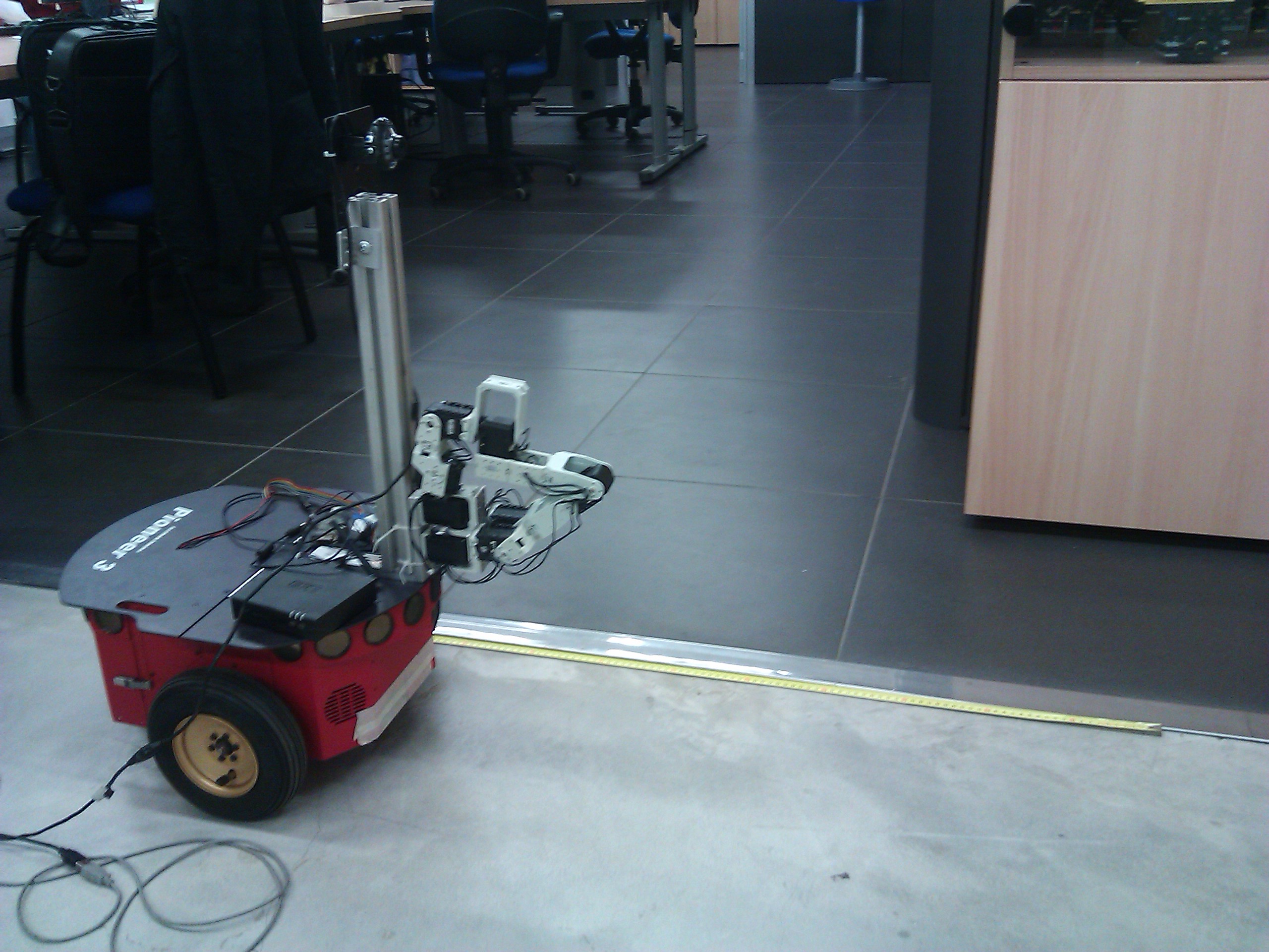
I tried to move the robot for one meter going to the straight direction and after I turned it on the right (90° around itself): http://www.youtube.com/watch?v=UMFbkt4-6s4

As you can see, viso2_ros monocular estimate 1.6626688201 meters along X direction instead of 1meter (see X position in console). In addiction to this, when I rotate it, it estimates a totally wrong position and orientation. My question is: how to tune all these parameters? I used the following:

Matcher parameters:
  nms_n                  = 3
  nms_tau                = 50
  match_binsize          = 50
  match_radius           = 200
  match_disp_tolerance   = 2
  outlier_disp_tolerance = 5
  outlier_flow_tolerance = 5
  multi_stage            = 1
  half_resolution        = 1
  refinement             = 1
Bucketing parameters:
  max_features  = 2
  bucket_width  = 50
  bucket_height = 50
Mono odometry parameters:
  camera_height    = 0.714
  camera_pitch     = 0
  ransac_iters     = 2000
  inlier_threshold = 1e-05
  motion_threshold = 100

I tried to set different values for inlier_threshold and motion_threshold without any success. Thankyou everybody.

edit retag flag offensive close merge delete

1 Answer

Sort by » oldest newest most voted
2

answered 2012-11-14 21:35:23 -0500

Stephan gravatar image

updated 2012-11-14 22:07:23 -0500

It is very likely that the monocular odometry of libviso2 does not work in your environment as it lacks features on the ground and your camera performs pure rotations without translation.

Monocular odometry and SLAM systems cannot estimate motion or position on a metric scale. All estimates are relative to some unknown scaling factor. libviso2 overcomes this by assuming a fixed transformation from the ground plane to the camera (parameters camera_height and camera_pitch). To introduce these values in each iteration the ground plane has to be estimated. That is why features on the ground are mandatory for the odometer to work.

Roughly the steps are the following:

  1. Find F matrix from point correspondences using RANSAC and 8-point algorithm
  2. Compute E matrix using the camera calibration
  3. Compute 3D points and R|t up to scale
  4. Estimate the ground plane in the 3D points
  5. Use camera_height and camera_pitch to scale points and R|t

In your case the odometer will fail at point 4. Unfortunately libviso2 does not provide sufficient introspection to signal this error to the user.

Another problem occurs when the camera performs just pure rotation: even if there are enough features, the linear system to calculate the F matrix degenerates.

To solve your problem you could either make sure that your environment has enough features and that your camera does not perform pure rotations or use a SLAM system such as PTAM which keeps a history and can use this to localize the camera in situations where no new 3D points could be calculated due to F matrix degeneration. A third option would be to use a stereo system with the stereo odometry of libviso2 as this does not need to estimate the ground plane and works for pure rotations, too.

Be aware that libviso2 was designed for wide angle cameras mounted on cars. I will add that information to the wiki to clarify these limitations.

edit flag offensive delete link more

Question Tools

1 follower

Stats

Asked: 2012-10-23 08:04:27 -0500

Seen: 2,044 times

Last updated: Nov 14 '12