ROS Resources: Documentation | Support | Discussion Forum | Index | Service Status | ros @ Robotics Stack Exchange
Ask Your Question
4

Improve gmapping results

asked 2012-07-18 03:16:08 -0500

Aslund gravatar image

updated 2012-07-18 03:46:53 -0500

joq gravatar image

Hey everyone

I am working with the ROS Navigation stack using a simulated environment in Stage. Initially I would have created a topic criticizing the precision of the AMCL localization stack, but after deeper research I found the error to occur from the map I have created with the GMapping.
The following image shows the comparison between the ideal image (blue) and the resulting map from GMapping (red). Interesting enough the data fed into the GMapping process are all ideal, no error in either the odometry or the laser scans.
Besides setting the number of particles to 150 I use the standard settings when executing the GMapping process. Actually I have tried to reduce the update frequency in the translation and angular rotation, but it did not change alot.

Comparision

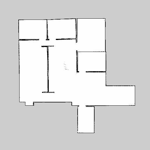
I have also tried to visualize quite primitively how I have traveled through the area. The black dot is the start and the numbers shows the order in which the different areas have been explored.

Comparision

Does anyone have any idea to how to improve the result of the GMapping process? So far it does not seem that impressive.

Regards
Sebastian Aslund

P.s my laser scanner is modeled to a SICK LMS200 with a range at 8m.
P.p.s Maybe it was an idea to show the results between a higher update frequency. The red figure shows the map with the standard update intervals. In the blue map the linear update is set to 0.2 and the angular update is set to 0.1.

Comparision

edit retag flag offensive close merge delete

Comments

Does it help to add more particles?

joq gravatar image joq  ( 2012-07-18 03:46:24 -0500 )edit

Depends. At 100 particles, I get improved results; however, at 150 I loose those results. I usually use this to start gmapping: rosrun gmapping _particles:=100 _linearUpdate:=0.1 _angularUpdate:=0.1.

allenh1 gravatar image allenh1  ( 2012-07-18 03:49:26 -0500 )edit

I have already increased the number of particles from 30 (the default value) to 150. But I can try raising it to 500 or so and see what happens.

Aslund gravatar image Aslund  ( 2012-07-18 03:50:04 -0500 )edit

You might want to create an entropy publisher to set it to 0. This can also help.

allenh1 gravatar image allenh1  ( 2012-07-18 03:50:18 -0500 )edit

What do you exactly mean by "create an entropy publisher to set it to 0"?

Aslund gravatar image Aslund  ( 2012-07-18 05:35:38 -0500 )edit

Entropy is a new topic in slam. It is a float64. The higher the entropy, the worse the odometry. If your odometry is perfect, then 0 will notify gmapping of this.

allenh1 gravatar image allenh1  ( 2012-07-18 05:45:27 -0500 )edit

@allenh1 While doing Hector_mapping, the odometry data gets totally ignored. So, how were you able to achieve the map with hector mapping using odometry?

tsdk00 gravatar image tsdk00  ( 2019-04-12 07:27:47 -0500 )edit

5 Answers

Sort by ยป oldest newest most voted
0

answered 2012-07-18 13:20:32 -0500

Aslund gravatar image

updated 2012-07-18 22:30:37 -0500

-- Second update to the responces --

Since it seemed that there were a consensus that higher particle count is not the way to go, then I went back to the beginning. I tried off with a particle count at 30, the default value. Instead the updates were lowered to 0.01. This results in the command _particles:=30 _linearUpdate:=0.1 _angularUpdate:=0.1 and the returned map is displayed below.

Comparision

I began to wonder. Now all my tests have been based on the ideal values, so I tried the same parameters on the noisy data. This gives the following map:

Comparision

The result in very surprising, especially because my noise is mostly focused on error in the rotation. It might be due to optimizations in the GMapping code towards noisy data, which might cause ideal data to be regarded as even more erroneous than actual erroneous data.
Below is the development in error. The seconds are reported 100 times to high, minor visualization error. Comparision

Secondly I have tried off the Hector SLAM mapping using the launch file supplied by allenh1. Somehow it did not work at all when i set the parameter "rosparam set use_sim_time true", so I had to run it without. With this I can only use the ideal values, I need simulation time to test with the noisy data.
Nevertheless I got the same results as allenh1 and here is the comparison with the ground truth:

Comparision

Since the tutorial launch file in Hector_SLAM sets use_sim_time to true I guessed this could the same, but apparently not, any obvious reasons why? The initial tests shows a good result using this SLAM method.

Edit: Thanks to the tip from Stefan I got Hector SLAM up and running with my erroneous data. Time to time I get a strange error:
Transform failed during publishing of map_odom transform: Unable to lookup transform, cache is empty, when looking up transform from frame [/base_laser_link] to frame [/odom_error]

Apparently it does not affect the mapping, but there is no visualization of the path. The result map is:

Comparision

It seems the long narrow path between waypoint 4 and 5 (see my original post) causes the SLAM process to become lost quite easily.
I tried to omit the odometry from the Hector mapping, while it removed some problems it brought new ones.

Comparision

Regards and thanks

Sebastian Aslund

edit flag offensive delete link more

Comments

Do you play back your bagfile with the --clock option appended? If not, sim time will not be published by rosbag and this can lead to all sorts of problems.

Stefan Kohlbrecher gravatar image Stefan Kohlbrecher  ( 2012-07-18 20:07:27 -0500 )edit

Thanks Stefan it solved the problem, I have updated my post with the noisy data.

Aslund gravatar image Aslund  ( 2012-07-18 22:32:12 -0500 )edit

Hector_Slam does not use odometry for state estimation, so it should not matter if odometry is available or not. How did you generate your noisy data?

Stefan Kohlbrecher gravatar image Stefan Kohlbrecher  ( 2012-07-18 22:35:40 -0500 )edit

My noisy data is generated quite simply. I read the laser data, add a noise based on a normal distribution to each range and finally publish to a seperate topic, here "base_scan_error". For the odometry I create a new frame "odom_error" with reference to "odom".

Aslund gravatar image Aslund  ( 2012-07-18 23:42:14 -0500 )edit

The "odom_error" frame is updated at each new speed command. Using the translational and rotational speed the error in each is calculated using a set of weights and sampled through a normal distribution. The pose in "odom_frame" is then updated with the calculated speed error and the time step.

Aslund gravatar image Aslund  ( 2012-07-18 23:47:05 -0500 )edit
3

answered 2014-08-06 09:06:05 -0500

zsaigol gravatar image

Not sure if you've got the same issue I had - but my fix here was to set the minimumScore parameter to a very large value.

edit flag offensive delete link more
1

answered 2012-07-18 07:36:35 -0500

allenh1 gravatar image

updated 2012-07-19 04:04:33 -0500

I mapped with hector slam. Using odometry with it, I was able to create this map:

image description

This is pretty close to the original. I don't have the ground truth image, so I cannot make any comparison locally, but, trusting my eyes, it seems to be a pretty good one. Playing with parameters in a launch file, you can probably improve it. Here is the launch file I used to create the above:

<?xml version="1.0"?>

<launch>

  <node pkg="hector_mapping" type="hector_mapping" name="hector_mapping" output="screen">

    <!-- Topic names -->
    <param name="scan_topic" value="base_scan" />    

    <!-- Frame names -->
    <param name="base_frame" value="base_laser_link" />
    <param name="odom_frame" value="odom"/>
    <param name="output_timing" value="false"/>

    <!-- Tf use -->
    <param name="use_tf_scan_transformation" value="true"/>
    <param name="use_tf_pose_start_estimate" value="false"/>
    <param name="pub_map_odom_transform" value="true"/>
    <param name="advertise_map_service" value="true"/>

    <!-- Map size / start point -->
    <param name="map_resolution" value="0.050"/>
    <param name="map_size" value="2048"/>
    <param name="map_start_x" value="0.5"/>
    <param name="map_start_y" value="0.5" />
    <param name="map_multi_res_levels" value="2" />

    <!-- Map update parameters -->
    <param name="update_factor_free" value="0.4"/>
    <param name="update_factor_occupied" value="0.9" />    
    <param name="map_update_distance_thresh" value="0.4"/>
    <param name="map_update_angle_thresh" value="0.06" />

    <!-- Debug parameters -->
    <!--
      <param name="pub_drawings" value="true"/>
      <param name="pub_debug_output" value="true"/>
    -->
  </node>

  <node pkg="hector_trajectory_server" type="hector_trajectory_server" name="hector_trajectory_server" output="screen">
    <param name="target_frame_name" type="string" value="/map" />
    <param name="source_frame_name" type="string" value="/base_link" />
    <param name="trajectory_update_rate" type="double" value="4" />
    <param name="trajectory_publish_rate" type="double" value="0.25" />
  </node>

  <node pkg="hector_geotiff" type="geotiff_node" name="hector_geotiff_node" output="screen" launch-prefix="nice -n 15">
    <remap from="map" to="/dynamic_map" />
    <param name="map_file_path" type="string" value="$(find hector_geotiff)/maps" />
    <param name="map_file_base_name" type="string" value="hector_slam_map" />
    <param name="geotiff_save_period" type="double" value="10" />
    <param name="draw_background_checkerboard" type="bool" value="true" />
    <param name="draw_free_space_grid" type="bool" value="true" />
  </node>

</launch>

To run the bag in simtime, use this command:

rosbag play <bagfile>.bag --clock
edit flag offensive delete link more

Comments

Hi there, I am working on a similar work. I am using LMS200 for my robot. I would like to know ,how did u implement the navigation stack in ros. Here is my email id: karthikeyan.yuvraj@gmail.com. This would make it easier for us to communicate. Thanks.

metal gravatar image metal  ( 2012-07-18 10:06:56 -0500 )edit

If you are asking how to install the Hector-slam stack, then the process is quite simple. For fuerte you can download the stack here: http://tu-darmstadt-ros-pkg.googlecode.com/svn/branches/fuerte/. For other you can use: http://tu-darmstadt-ros-pkg.googlecode.com/svn/trunk/hector_slam/.

Aslund gravatar image Aslund  ( 2012-07-18 12:37:07 -0500 )edit

The rest is decribed here: http://www.ros.org/wiki/hector_slam. Ps. if you are talking concretely about the foundamental navigation part, then this tutorial makes it all a walk in the park: http://www.ros.org/wiki/navigation

Aslund gravatar image Aslund  ( 2012-07-18 12:38:44 -0500 )edit
0

answered 2012-07-18 04:50:05 -0500

dornhege gravatar image

If you have a good source of incoming data, you should fit the motion model to it. That are the srr,srt,... parameters. You should lower them to reflect the actual error you have.

Also the laser should fit the scale of the environment, so it sees as much as possible. The LMS200 max range is 80m, AFAIK only the prototypes had 8m.

PS: If you just want to have a perfect map, you can just use your blue ground truth image and convert it to pgm + write the yaml file.

edit flag offensive delete link more

Comments

While the data right now is ideal, then I have also simulated errors in the odometry and laser scans. Ideal values are merely used to evaluate the precision and stability of the different parts of the navigation stack.

Aslund gravatar image Aslund  ( 2012-07-18 05:38:06 -0500 )edit

OK, in that case, obviously leave the real values.

dornhege gravatar image dornhege  ( 2012-07-18 06:02:32 -0500 )edit

I am a bit puzzled about the range of the sick lms200 scanner. The default in-built model of the sick laser in stage have the maximum range set to 8m. I just found a site referring to a max range on 10m with 10% reflection and you mention 80m. I only have hands-on expirience of the Hokuyo scanner.

Aslund gravatar image Aslund  ( 2012-07-18 06:39:41 -0500 )edit
0

answered 2012-07-18 05:50:28 -0500

Aslund gravatar image

-- Updates in the response the comments and tips so far --

I have tried to run the data with _particles:=100 _linearUpdate:=0.1 _angularUpdate:=0.1 and got the following result:

Comparision

Furthermore have I increased the number of particles to 500 and kept the updates at the default values. This gives the following result:

Comparision

Apparently an increased particle count helps against rotational deviations while increased updates have little effect, seems strange.
To those who might be interested in the data, then the bag can be downloaded here. The topics are /odom and /base_scan while the erroneous data are on the topics /odom_error and /base_scan_error.

So far thanks a lot for your ideas and thoughts.

edit flag offensive delete link more

Question Tools

3 followers

Stats

Asked: 2012-07-18 03:16:08 -0500

Seen: 8,224 times

Last updated: Apr 12 '19