
imu complementary and madgwick filter outputs skewed north
Hello,
I wanted to compare the outputs of imu_complementary_filter and imu_madgwick_filter so I made a launch file that launches both same filters and I remapped the output from each filter to their respective names like:
<remap from="/imu/data" to="/imu/complementary" />
for complementary filter and
<remap from="/imu/data" to="/imu/madgwick" />
for madgwick filter.
I also recompiled madgwick filter and changed the frame_id to 'base_imu_filter_madgwick' and I am broadcasting the following transformation:
<node pkg="tf" type="static_transform_publisher" name="odom_to_base_imu_link_madgwick" args="0.3 0 0 0 0 0 /odom /base_imu_link_madgwick 100"/>
So I can visualize both orientation figures side to side. (notice the 0.3 on the side.
At the beginning, the orientations output from each filter was shifted from each other, however adding
to the config of madgwick filter solved the problem. (the imu complementary filter outputs nwu, and it can not be changed with parameters)
I am also using a custum imu, that bridges the raw values to ros, after: mag offset compensation and soft iron compensation is performed.
Also, I had to edit the code of complementary_filter.cpp and changed the thresholds for the steady_state
const double ComplementaryFilter::kAngularVelocityThreshold = 0.2; const double ComplementaryFilter::kAccelerationThreshold = 0.6; const double ComplementaryFilter::kDeltaAngularVelocityThreshold = 0.02;
basically I increased those values until /imu/steady_state topic published true, while the sensor was at rest, to make the bias estimation part work,
I am also passing raw values at 100hz.
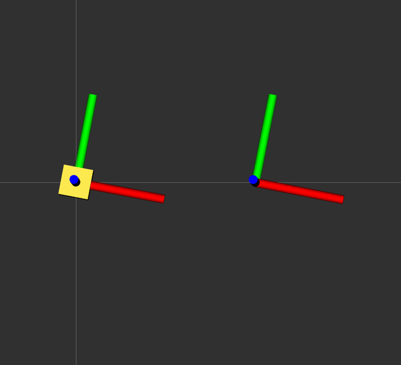
The one on the left is output of complementary filter. (with the box) the one on the right is madgwick filter.
The sensor is oriented to 0degree north. On the rviz screen right side is north.
So here are my questions:
The yaw is always skewed from north like 5-10 degrees. I have calibrated and recalibrated my sensor, but it is still always 5-10 skewed from north (measured with iphone) Is it because my hard iron compensation is wrong?
What are some typical imu frequencies to feed to this filter? I started with 10hz, now using 100hz, and I noticed the 100hz converges faster, naturally. I could potentially push my sensor to 400hz.
In the video, it shows the complementary filter being magnetic field disturbance resistant, but in my tests of holding the a metal spoon over the sensor distorts both filter outputs, actually on the complementary filter, there is more distortion than the madgwick, but the complementary filter distortion is yaw only.
are there any other references / documentation / config files / code on these filters except the pages at ros site, and their respective github pages. I read the code on both to make it work, but it could be nice if I could see few other implementations launch files, like typical gains, etc.
Best Regards, C.

Hello @wintermute, did you find the answer for Q1? Thanks in advance.
Hello @akosodry, yes the skew was due to ... I was using iphone compass for reference. The iphone compass was skewed. There was also an iron nail in the table that I used, that was part of it.
however I found no evidence of "magnetic field disturbance resistance" in the filter, but again i could be wrong.
best regards, C.