
Ghost obstacles on costmap
Hi everyone,
Please give me some advices for this problem with ghost obstacles.
My mobile robot is working with ROS (Kinetic, Ubuntu 16.0.4) using Sick sensor. My robot uses 2 Sick sensor, one is in the right-upper corner and another one is in left-bottom corner. I use ira_laser_tools to merge data of these 2 laser scanners.
However, I am stucking at one problem: ghost obstacles appear on the costmap, and this ghost obstacle is relative to my mobile robot. If my robot moves, the ghost obstacle relatively follow. It causes mobile robot try to avoid obstacles even though there is no real obstacles.
I have tried to use some different laser-filter packages, but this problem still happen.
Can you please give me some suggestion ?
Thanks in advances
I took a video about my error (ghost obstacle) as in the link below:
https://www.youtube.com/watch?v=THt7o...
And, the picture within the indication for ghost obstacles here:
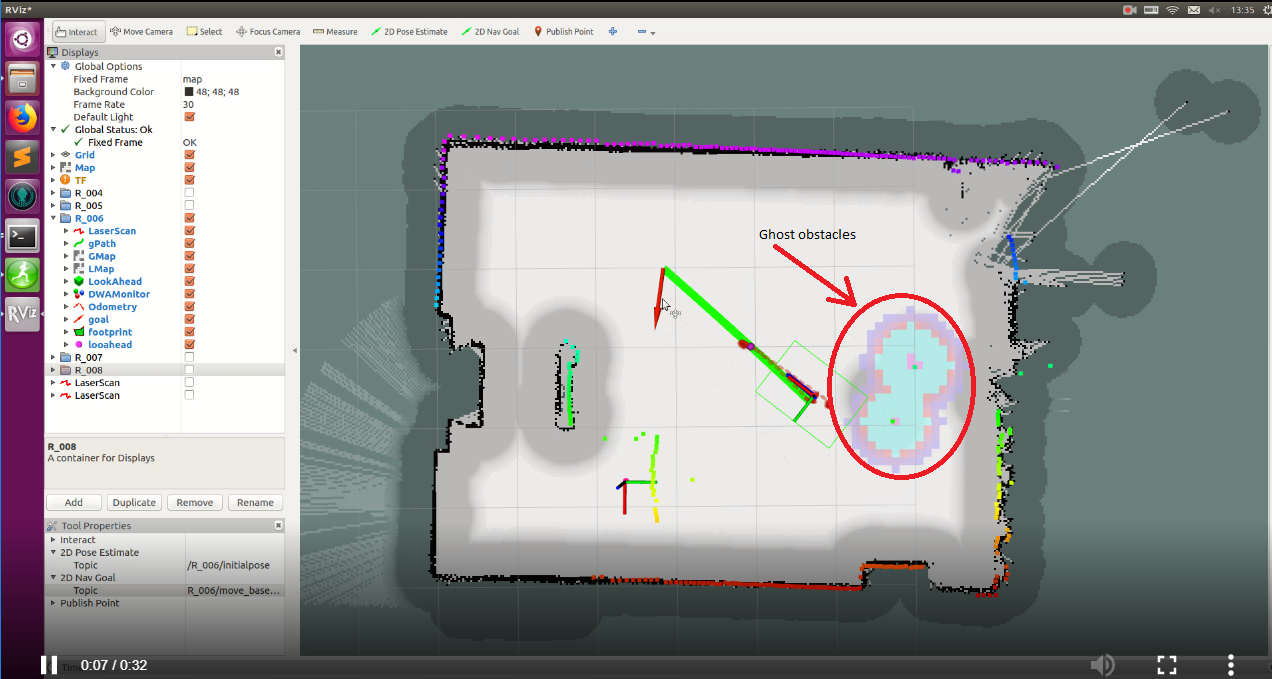
And, the costmap configuration:
costmap_common_params:
footprint: [[0.44, 0.34], [0.44, -0.34], [-0.44, -0.34], [-0.44, 0.34] ]

footprint_padding: 0.0

transform_tolerance: 0.2
map_type: costmap

obstacle_layer:
 enabled: true
 obstacle_range: 1.5
 raytrace_range: 3.0
 inflation_radius: 0.2
 track_unknown_space: true
 combination_method: 1
 min_obstacle_height: 0.1
 max_obstacle_height: 0.5

 observation_sources: laser_scan_sensor
 laser_scan_sensor: {data_type: LaserScan, topic: scan, marking: true, clearing: true}


inflation_layer:
  enabled:              true
  cost_scaling_factor:  10.0  # exponential rate at which the obstacle cost drops off (default: 10)
  inflation_radius:     0.6 # max. distance from an obstacle at which costs are incurred for planning paths.

static_layer:
  enabled:              true
  map_topic:            "map"

rgbd_obstacle_layer:

  enabled:               true

  voxel_decay:           0.4     #seconds if linear, e^n if exponential

  decay_model:           0      #0=linear, 1=exponential, -1=persistent

  voxel_size:            0.05   #meters

  track_unknown_space:   true   #default space is unknown

  observation_persistence: 0.0  #seconds

  max_obstacle_height:   2.0    #meters

  unknown_threshold:     15     #voxel height

  mark_threshold:        0      #voxel height

  update_footprint_enabled: true

  combination_method:    1      #1=max, 0=override

  obstacle_range:        2.0    #meters

  origin_z:              0.0    #meters

  publish_voxel_map:     true   # default off

  transform_tolerance:   0.2    # seconds

  mapping_mode:          false  # default off, saves map not for navigation

  map_save_duration:     60     #default 60s, how often to autosave

  observation_sources:   rgbd1_clear rgbd1_mark rgbd2_clear rgbd2_mark

  rgbd1_mark:

    data_type: PointCloud2

    topic: cam_1/depth/color/points

    marking: true

    clearing: false

    min_obstacle_height: 0.15     #default 0, meters

    max_obstacle_height: 2.0     #defaule 3, meters

    expected_update_rate: 0    #default 0, if not updating at this rate at least, remove from buffer

    observation_persistence: 0.0 #default 0, use all measurements taken during now-value, 0=latest

    inf_is_valid: false          #default false, for laser scans

    clear_after_reading: true    #default false, clear the buffer after the layer gets readings from it

    voxel_filter: true           #default off, apply voxel filter to sensor, recommend on

  rgbd1_clear:

 data_type: PointCloud2

    topic: cam_1/depth/color/points

    marking: false

    clearing: true

    min_z: 0.1                   #default 0, meters

    max_z: 7.0                   #default 10, meters

    vertical_fov_angle: 0.7      #default 0.7, radians

    horizontal_fov_angle: 1.04   #default 1.04, radians

    decay_acceleration: 1.       #default 0, 1/s^2. If laser scanner MUST be 0

    model_type: 0                #default 0 (depth camera). Use 1 for 3D Lida ...
I guess it would help to see an image of your problem, as well as a description of what is there "in the real world". Also, maybe share your costmap configuration. That the obstacle is moving with the robot is suggesting that it is continuously seen by the scanner. Can you verify this?
I've come across this in multiple scenarios:
ScanShadowsFiltercan help there)obstacle_rangeandraytrace_rangeobstacle_layermaybe it can be narrowed down to one of those?
Thank mgruhler so much for your quick help, I will prepare those kinds of data and update soon
@Getchbold NT: please attach your screenshot directly to the question. I've given you sufficient karma.
Thank you so much @gvdhoorn
I updated the video and picture about error and cost_map configuration @mgruhler
quite obviously, the laser scanner is actually measuring something there. So the costmap is actually doing what it is supposed to.
So you need to figure out where those readings are coming from.
If this is a problem that occurs that often, you might probably have to use a laser filter to get rid of those (single point) measurements. The ScanShadowsFilter can really help there.
What sensor are you using exactly?
@mgruhler thank you so much for your answer
I am using Sick sensor.
Our laboratory does not has mirror and glass.
This problem now always happen, I cannot know how to solve this problem. I am quite new with lidar sensor and laser filter. Can you please tell me clearly how to use ScanShadowsFilter to remove these single points?.
I can see this configuration of ScanShadowsFilter, but I do not actually whether this shadow_filter is called or not ?
scan_filter_chain:
name: shadows
type: ScanShadowsFilter
params:
min_angle: 5
max_angle: 175
neighbors: 1
window: 1
name: dark_shadows
type: LaserScanIntensityFilter
params:
lower_threshold: 100
upper_threshold: 50000
disp_histogram: 0
The costmap configuration is used as default, I did not change anything
Thank you so much
Yes, a Sick sensor, but which model? LMSXXX? S300? S3000? MSR? Seeing that the scan is actually 360°, it is non of the former, but maybe an MSR?
There is a tutorial describing the ScanShadowsFilter. Then you obviously need to fix the remappings in the respective nodes. Please update your question (or post a new one) if you have troubles with setting this up...